Understanding Proximity Sensors and Push Button Switches
In industrial automation and control systems, two fundamental components for initiating and detecting actions are proximity sensors and push button switches. A proximity sensor is a non-contact device that detects the presence or absence of an object within its sensing range, typically using electromagnetic fields, light, or sound. Common types include inductive, capacitive, and photoelectric sensors. Conversely, a push button switch is an electromechanical device operated by physical pressure from an operator to make or break an electrical circuit. They come in various forms such as momentary and maintained contact types. Understanding the operational principles of these devices is crucial before delving into their wiring methodologies, as it dictates the choice of wiring configuration, power requirements, and integration with controllers like PLCs (Programmable Logic Controllers).
Core Wiring Principles and Safety Precautions
Prior to any wiring activity, adhering to core electrical safety principles is non-negotiable. Always ensure the power supply is completely isolated and locked out using proper procedures. Verify the voltage and current ratings of both the sensor/switch and the power source to prevent damage. Use appropriate wire gauges as per the current load and follow local electrical codes and standards (e.g., NEC, IEC). For proximity sensors, it's vital to identify whether they are sourcing (PNP) or sinking (NPN) types, as this determines how they interface with the PLC's input card. Similarly, push button switches must be identified as normally open (NO) or normally closed (NC) contacts. Proper grounding and shielding for sensor cables, especially in environments with high electromagnetic interference, are essential for reliable operation.
Wiring a 3-Wire DC Proximity Sensor
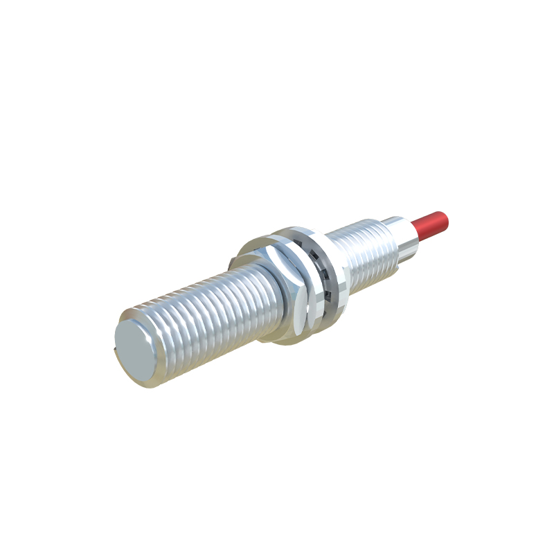
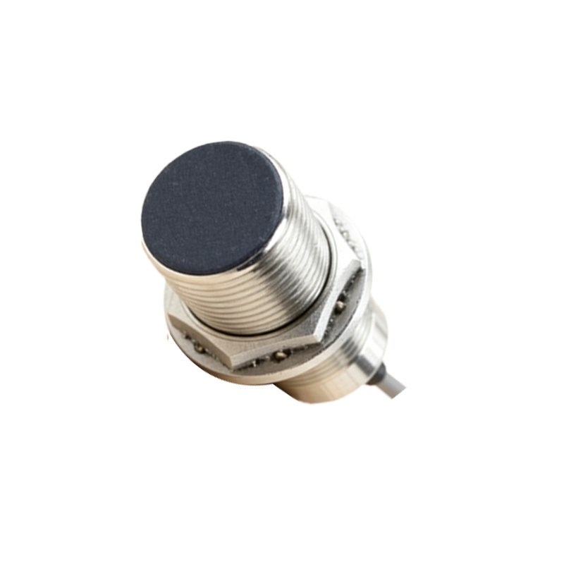
The three-wire DC proximity sensor is the most common type in industrial settings. It has three distinct wires: brown (or red) for positive DC supply (+V), blue for negative DC supply (0V or common), and black (or white) for the output signal. For a PNP (sourcing) sensor, the black wire outputs a positive voltage (+V) when an object is detected. To wire it, connect the brown wire to the positive DC terminal (e.g., +24VDC), the blue wire to the negative DC terminal (0VDC), and the black output wire to the input terminal of the PLC. The PLC input's common terminal is then connected to the 0VDC. For an NPN (sinking) sensor, the black wire sinks current to 0V when activated. Here, the brown and blue wires connect the same way, but the black output wire connects to the PLC input, and the PLC input's common is connected to the positive supply (+24VDC). Always refer to the manufacturer's datasheet for definitive color codes and specifications.
Wiring a Standard Push Button Switch
A simple push button switch typically has two terminals for a single-pole, single-throw (SPST) configuration. Wiring a normally open (NO) momentary push button involves connecting one terminal to the power source (e.g., +24VDC) and the other terminal to the load, which could be a PLC input, a relay coil, or an indicator lamp. The other side of the load is then connected to the power common (0VDC). When the button is pressed, the circuit closes, allowing current to flow and activate the load. For a maintained-contact switch, the circuit remains closed until the button is pressed again. For applications requiring both NO and NC functions, a push button with multiple terminals is used. It is common practice to use the NC contact for safety-critical functions like emergency stops, where the circuit is normally closed and opens to stop machinery.
Integrating Sensors and Switches with a PLC Input Module
Integration with a PLC is a standard practice. Most modern PLC input modules are designed to be compatible with both sourcing (PNP) and sinking (NPN) field devices, but the common terminal wiring must be configured correctly. For a system using primarily PNP proximity sensors and push buttons, the common terminal of the PLC's DC input module should be connected to the 0VDC. Each sensor's output wire and one side of each push button contact are then connected to individual PLC input points. The other side of the push button contacts are jumpered together and connected to the +24VDC supply. This creates a circuit where activating any device applies +24VDC to the respective PLC input, signaling a logic HIGH or '1' state. The PLC program is then written to interpret these input signals and execute the desired control logic for outputs like motors, valves, or alarms.