Understanding Photoelectric Sensors in PLC Systems
Photoelectric sensors are indispensable components in modern industrial automation, serving as the primary eyes for Programmable Logic Controllers (PLCs). These sensors detect the presence, absence, or distance of objects using a light transmitter and receiver, converting optical signals into electrical signals that the PLC can process. Common types include through-beam, retro-reflective, and diffuse reflective sensors, each suited for specific applications based on range, environmental conditions, and target material. Integrating these sensors with a PLC requires a solid grasp of their operational principles, output configurations (such as NPN or PNP sinking/sourcing), and voltage requirements (typically 10-30V DC). Proper selection ensures reliable detection, minimizes false triggers, and enhances the overall efficiency of automated systems, from packaging lines to robotic assembly cells.
Essential Components and Wiring Preparations
Before initiating the wiring process, gather all necessary components: the photoelectric sensor, PLC unit, power supply (matching the sensor's voltage rating, e.g., 24V DC), cables, connectors, and tools like wire strippers and multimeters. Always refer to the manufacturer's datasheets for both the sensor and PLC to confirm specifications such as input type (digital or analog), current ratings, and terminal designations. Safety is paramount—ensure the power is completely disconnected to prevent electrical hazards. Verify the sensor's output type: NPN (sinking) outputs connect the load to the positive voltage, while PNP (sourcing) outputs connect it to ground. Additionally, check if the sensor requires a separate control line for functions like teach-in or timing modes, which may involve additional wiring to PLC input points.
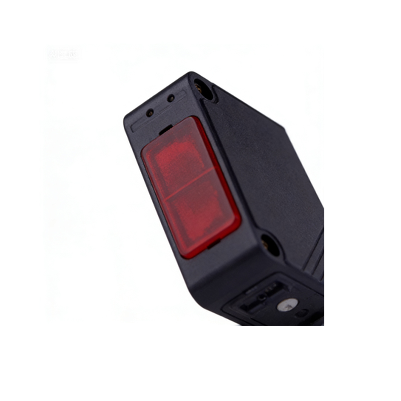
Step-by-Step Wiring Procedure for NPN and PNP Sensors
For NPN sensors, start by connecting the brown wire (typically positive) to the DC power supply's positive terminal (e.g., 24V+). Link the blue wire (negative) to the power supply's common ground. The black wire (output signal) should be routed to the PLC's input terminal, while the PLC input's common point is tied to the positive voltage. This configuration allows the sensor to sink current to ground when activated, signaling the PLC. For PNP sensors, the brown wire still connects to positive, and the blue to ground, but the black output wire links to the PLC input, with the PLC input common connected to ground. Here, the sensor sources current to the PLC upon detection. Always use shielded cables in noisy industrial environments to reduce electromagnetic interference, and secure connections tightly to avoid loose wires that could cause signal drops or short circuits.
Integrating Sensor Signals with PLC Input Modules
PLC input modules are designed to receive digital or analog signals from sensors. For digital photoelectric sensors, the wiring feeds into a discrete input card. Confirm the card's compatibility with the sensor's voltage level—most industrial PLCs accept 24V DC inputs. After physical wiring, program the PLC to recognize the sensor's signal. For instance, in ladder logic, assign the corresponding input address (e.g., I0.0) to trigger actions like activating a motor or counter. For analog sensors measuring distance or intensity, connect the output wires to an analog input module, ensuring proper scaling in the PLC software to convert voltage (e.g., 0-10V) or current (4-20mA) signals into meaningful data. Test the integration by observing the PLC's input indicators or software monitor to verify signal stability upon object detection.
Troubleshooting Common Wiring Issues and Best Practices
Even with careful installation, issues may arise. If the PLC fails to detect sensor signals, first check power connections with a multimeter to ensure correct voltage at the sensor terminals. Inspect for wiring errors, such as reversed polarity or loose terminals, which can prevent proper operation. Environmental factors like dust, moisture, or ambient light might interfere with optical performance—clean the sensor lens regularly and consider using models with built-in filters for harsh conditions. Implement best practices: label all wires clearly, maintain proper cable management to avoid strain, and adhere to international standards (e.g., IEC 61131 for PLC systems). Periodically validate the system through functional tests, documenting any adjustments to streamline future maintenance and ensure long-term reliability in automated processes.