Introduction to Photoelectric Sensor Labeling
In industrial automation and control systems, photoelectric sensors are indispensable components for detecting the presence, absence, or position of objects without physical contact. Proper electrical labeling of these sensors is not merely a regulatory formality but a critical practice for ensuring system safety, reliability, and maintainability. Electrical labels serve as the primary source of information for installation, troubleshooting, and maintenance personnel. They convey vital data about the sensor's electrical characteristics, wiring requirements, and operational parameters. A well-labeled sensor reduces downtime, prevents miswiring that could lead to equipment damage or safety hazards, and facilitates efficient system integration. This guide delves into the essential elements and best practices for electrical labeling specific to photoelectric sensors, tailored for engineering professionals.
Core Information on Electrical Labels
The electrical label on a photoelectric sensor must provide unambiguous and accessible information. At a minimum, it should include the following key data points. The sensor's model number and part number are fundamental for identification and procurement of exact replacements. The supply voltage range (e.g., 10-30 VDC) must be clearly stated to prevent application with incompatible power sources. The current consumption or maximum load current is crucial for proper power supply sizing and circuit protection. The output type and configuration (e.g., NPN sinking, PNP sourcing, normally open (NO), normally closed (NC)) must be explicitly indicated, as this dictates the wiring scheme to the programmable logic controller (PLC) or other control devices. The connection diagram or terminal designations (e.g., +V, 0V, OUT, SHIELD) are perhaps the most critical element on the label, providing immediate visual guidance for correct wiring. International protection ratings, such as the IP (Ingress Protection) code (e.g., IP67), should be included to inform users about the sensor's suitability for specific environmental conditions like dust or water exposure.
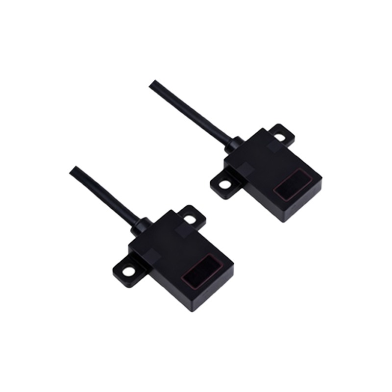
Standards and Regulatory Compliance
Adherence to international and regional standards is non-negotiable in industrial applications. Electrical labeling for photoelectric sensors must comply with standards such as IEC 61346 (structuring principles and reference designations), IEC 60445 (basic and safety principles for man-machine interface), and various regional directives like the European Union's Machinery Directive and Low Voltage Directive. These standards often mandate the use of specific symbols, color codes, and terminology. For instance, the use of standardized symbols for DC power, ground, and output signals enhances comprehension across language barriers. Compliance ensures that the sensor meets minimum safety requirements and can be legally integrated into machinery for sale in regulated markets. Engineers must verify that the labeling on selected sensors conforms to the standards applicable in their operational region.
Label Durability and Legibility
The technical content of a label is useless if the label itself fails in the operating environment. Photoelectric sensors are frequently deployed in harsh conditions involving oil, coolant, UV exposure, extreme temperatures, and physical abrasion. Therefore, the label material and printing method must be chosen for exceptional durability. Common solutions include polyester or polyimide labels with permanent adhesive and thermal-transfer or laser etching for the printed information. The text and symbols must remain legible throughout the sensor's expected service life. Font size, contrast (typically black on white or white on black), and the use of internationally recognized pictograms contribute to long-term legibility. A label that fades, peels, or becomes unreadable compromises the entire safety and maintenance protocol.
Best Practices for System Integration and Documentation
Beyond the sensor's individual label, engineers must consider labeling within the broader control panel and machine system. Consistent labeling philosophy should extend from the sensor's terminals back to the power supply and PLC input cards. This often involves using wire markers, cable tags, and panel legends that correspond to the designations on the sensor label. For example, a sensor with output terminal "OUT" should be connected to a wire labeled consistently, which then terminates at a clearly marked PLC point. This end-to-end traceability is invaluable for troubleshooting. Furthermore, the information from the electrical label should be meticulously recorded in system documentation, including electrical schematics, bills of materials, and maintenance manuals. Digital twins and asset management systems can store this data, linking the physical sensor's label to its digital record for lifecycle management.
Conclusion and Future Trends
Meticulous electrical labeling is a cornerstone of professional engineering practice in automation. For photoelectric sensors, it bridges the gap between the device's inherent capabilities and its safe, effective application. As technology evolves, trends like Industry 4.0 and the Industrial Internet of Things (IIoT) are influencing labeling practices. The emergence of smart sensors with integrated communication protocols (e.g., IO-Link) adds layers of digital data accessible via software, but the physical electrical label remains the fundamental, always-available source of critical connection and power information. Engineers must continue to prioritize clear, compliant, and durable labeling as an integral part of system design, ensuring that both humans and machines can interact with these essential components reliably for years to come.