Fundamental Operating Principle
Inductive proximity sensors are non-contact electronic devices designed to detect the presence of ferrous and non-ferrous metallic objects without physical contact. The core of their operation lies in electromagnetic induction. The sensor's active face contains a coil that is part of an oscillating circuit, generating a high-frequency electromagnetic field. When a metal target enters this field, eddy currents are induced on the surface of the target. These eddy currents draw energy from the sensor's oscillating circuit, causing a measurable change in its amplitude. An internal evaluation circuit detects this amplitude damping and triggers a switching signal, typically through a solid-state output. This principle makes them exceptionally reliable for detecting metals like steel, aluminum, brass, and copper, though with varying sensing distances based on the target material's conductivity and permeability.
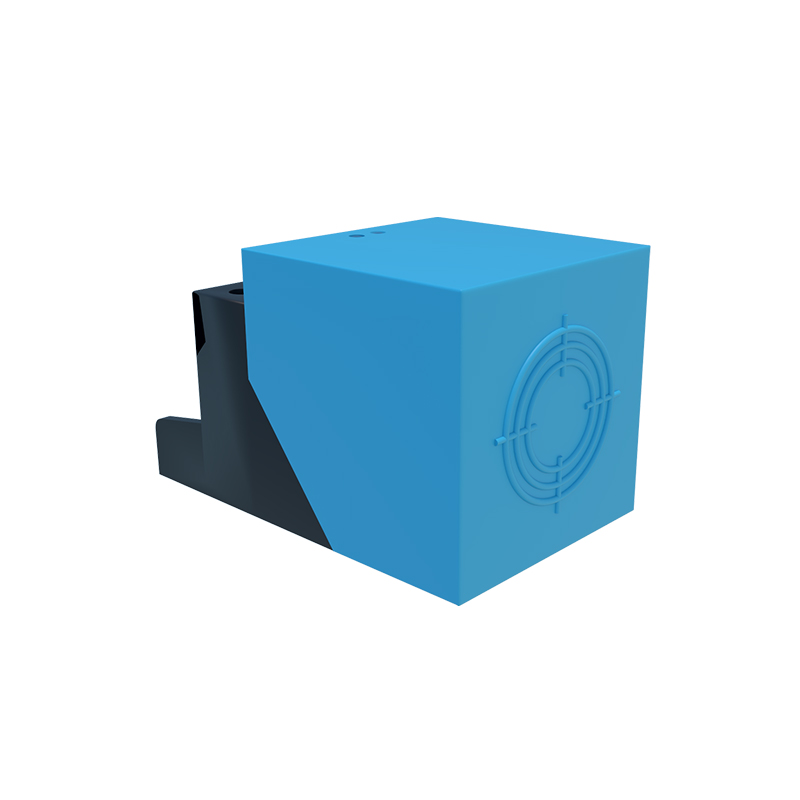
Key Technical Characteristics and Specifications
Understanding the specifications is crucial for proper sensor selection. The nominal sensing distance (Sn) is a primary parameter, defined under standardized conditions with a mild steel target. It's vital to note that the effective sensing distance can be reduced for non-ferrous metals. Another critical specification is the repeat accuracy, which defines the sensor's consistency in triggering at the same point. Factors like temperature stability, switching frequency (how many times per second it can detect an object), and housing material (often nickel-plated brass, stainless steel, or PBT plastic) significantly impact performance in harsh industrial environments. Most sensors feature built-in protection against short-circuits, overloads, and reverse polarity, enhancing their durability in demanding automation setups.
Common Industrial Applications and Use Cases
The robustness and reliability of inductive sensors make them ubiquitous in factory automation. A primary application is in position sensing on production lines, such as verifying the presence of a metal part on a conveyor, counting metal components, or detecting the end position of a cylinder. They are indispensable in machine tools for tool breakage detection and spindle positioning. In material handling, they monitor pallet presence and control sorting gates. Their sealed, rugged housings allow use in dirty, oily, or wet conditions where optical sensors might fail, such as in metalworking, automotive assembly, and packaging machinery. They provide the essential "go/no-go" feedback for PLCs and control systems.
Advantages Over Other Sensor Technologies
Inductive sensors offer distinct benefits that solidify their role in metal detection. Their primary advantage is complete insensitivity to non-metallic materials like dust, wood, plastic, or liquids, preventing false triggers. They are mechanically robust, with no moving parts to wear out, leading to a long operational life even under constant vibration or shock. The non-contact nature eliminates physical wear on both the sensor and the target. Compared to capacitive sensors, they are unaffected by humidity or material density changes. While photoelectric sensors have longer ranges, inductive sensors excel in environments with heavy contamination, coolant mist, or where the target is small, shiny, or in close proximity.
Critical Selection Criteria for Engineers
Selecting the right inductive sensor requires a systematic approach. First, identify the target material and size, as this determines the required sensing distance and may necessitate a factor correction. The installation environment is next; choose an appropriate housing material (e.g., stainless steel for corrosive settings) and ingress protection rating (IP67 or IP69K for washdown areas). Electrical characteristics are paramount: select the correct operating voltage (10-30V DC or 20-250V AC), output type (PNP/NPN, NO/NC), and connection method (pre-wired cable or quick-disconnect). Physical constraints like flush or non-flush mounting capability and housing shape (barrel, rectangular, ring) must fit the mechanical design. Finally, consider special features like weld-field immunity for robotic welding cells or analog outputs for distance measurement.
Installation and Maintenance Best Practices
Correct installation maximizes sensor performance and longevity. Ensure the sensor is mounted securely to minimize vibration. For flush-mounted sensors, maintain the recommended clearance from surrounding metal to prevent shielding effects. Always power the sensor with the correct voltage and observe polarity for DC types. During wiring, use shielded cables in electrically noisy environments and keep them separate from power lines. Routine maintenance is minimal but should include periodic cleaning of the sensing face to remove buildup of metal chips or grease that could reduce the effective range. Check for physical damage to the housing and verify the switching signal under normal operating conditions as part of a preventative maintenance schedule.