Introduction to Photoelectric Sensors and Optocouplers
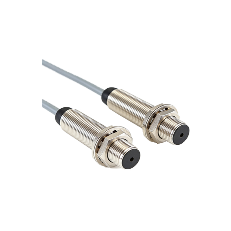
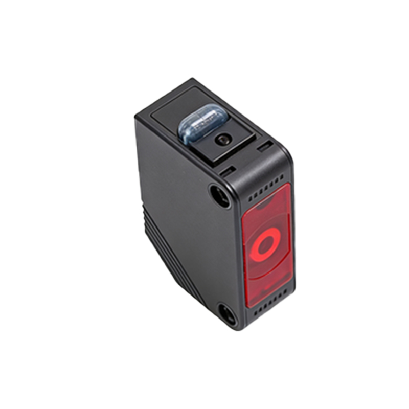
Photoelectric sensors are ubiquitous in industrial automation, serving as the eyes of a control system. They detect the presence, absence, or distance of an object using a light transmitter and receiver. Common types include through-beam, retro-reflective, and diffuse reflective sensors. Their outputs are typically transistor-based, providing a switching signal (NPN sinking or PNP sourcing) to a controller like a PLC. However, in electrically noisy environments or when interfacing circuits with different voltage levels and grounds, a direct connection can introduce noise, cause malfunctions, or even damage sensitive control electronics. This is where the optocoupler becomes an indispensable component.
The Role of the Optocoupler in Signal Isolation
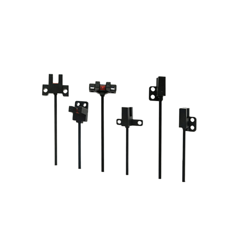
An optocoupler, also known as an opto-isolator, is a semiconductor device that transfers electrical signals using light waves. It contains an LED (light-emitting diode) on its input side and a photosensitive component, such as a phototransistor or photodiode, on its output side. These two elements are housed in a light-tight package. When current flows through the input LED, it emits infrared light, which activates the output phototransistor, allowing current to flow in the output circuit. The key advantage is that there is no electrical connection between the input and output; they are galvanically isolated. This isolation barrier, typically rated from a few hundred to several thousand volts, prevents ground loops, suppresses voltage transients, and eliminates noise coupling from high-power machinery to low-voltage logic circuits.
Circuit Design Considerations for NPN Sensor Interface
Connecting an NPN (sinking) output photoelectric sensor to an optocoupler is a common requirement. In this configuration, the sensor's output transistor acts as a switch to ground. The circuit is designed as follows. The positive supply voltage (e.g., 24V DC) is connected to the sensor's brown wire. The sensor's blue wire is connected to the power supply common (0V). The sensor's black (output) wire is connected to the anode of the optocoupler's internal LED. The cathode of this LED is then connected to the positive supply rail (the same 24V) through a current-limiting resistor. This resistor is critical. Its value is calculated using Ohm's Law: R = (Vsupply - Vf_LED - Vce_sat) / If. Where Vsupply is 24V, Vf_LED is the forward voltage of the optocoupler's input LED (typically 1.2V-1.5V), Vce_sat is the saturation voltage of the sensor's output transistor (typically<1V), and If is the desired forward current for the LED (usually between 5mA and 20mA, as per the optocoupler datasheet). When the sensor detects an object, its NPN transistor turns ON, sinking current. This completes the path from the 24V rail, through the resistor and LED, through the sensor transistor to ground, illuminating the LED and activating the optocoupler's output.
Circuit Design Considerations for PNP Sensor Interface
For a PNP (sourcing) output sensor, the output transistor sources current from the positive supply. The wiring differs accordingly. The sensor's brown and blue wires are connected to 24V and 0V as before. The sensor's black output wire now provides a positive voltage when active. This wire is connected to the anode of the optocoupler's LED. The cathode of the LED is then connected directly to the power supply common (0V) through the same crucial current-limiting resistor. The calculation for the resistor is simpler: R = (Vsensor_on - Vf_LED) / If. Here, Vsensor_on is the voltage at the sensor output when active (close to 24V), and Vf_LED is the LED forward voltage. When the PNP sensor is active, it sources current, which flows from its output, through the LED and resistor, to ground, thus activating the optocoupler.
Selecting the Output Side Components and Load
The output side of the optocoupler must be configured to interface with your controller, often a PLC digital input or a microcontroller. The collector of the phototransistor is typically connected to a pull-up resistor (e.g., 10kΩ) tied to the controller's logic voltage (e.g., 3.3V or 5V). The emitter is connected to the controller's ground. The collector output is then connected to the digital input pin. When the optocoupler's input LED is lit, the phototransistor saturates, pulling the collector voltage low (near 0V), representing a logic '0' or active state. When the LED is off, the phototransistor is off, and the pull-up resistor pulls the voltage high to the logic level, representing a logic '1' or inactive state. Ensure the optocoupler's output current rating (IC) and voltage rating (VCEO) exceed the requirements of this interface circuit. For driving heavier loads like relays, an additional buffer transistor may be required on the optocoupler's output.
Practical Implementation and Troubleshooting Tips
Always begin implementation by consulting the datasheets for both the photoelectric sensor and the chosen optocoupler. Verify voltage ratings, current limits, and output types. Use a breadboard or terminal strip for initial testing. Common issues include the optocoupler not activating, often due to an incorrectly calculated or placed current-limiting resistor on the input side, or reversed polarity of the LED. Use a multimeter to check for voltage at the sensor output when active and to measure the current through the LED circuit. Another frequent problem is incorrect logic state at the controller; a logic '1' when expecting a '0'. This usually indicates a wiring error on the output side, such as a missing pull-up resistor or incorrect connection to the PLC input type (sinking vs. sourcing). For long cable runs in high-noise environments, consider using shielded cables and connecting the shield to a proper earth ground at one end only to further enhance noise immunity provided by the optocoupler.