Introduction to Retro-Reflective Photoelectric Sensing
A retro-reflective photoelectric sensor, often termed a "reflex" sensor, is a cornerstone of industrial automation for object detection. Its operation hinges on a simple yet elegant principle: a built-in emitter projects a beam of light towards a specialized reflector. This reflector, unlike a standard mirror, is designed to return the light beam directly along its original path, regardless of the angle of incidence, back to a built-in receiver within the same sensor housing. This configuration allows for reliable detection over considerable distances with a single, compact unit, making it highly efficient for applications like conveyor belt monitoring, packaging, and material handling.
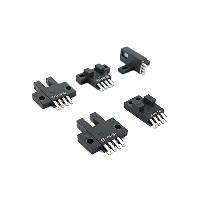
Core Components and Their Schematic Symbols
Understanding the schematic begins with its fundamental components. The emitter is typically represented by an LED symbol, often an infrared (IR) LED, pointing outward. The receiver is usually depicted as a phototransistor or photodiode symbol. The defining element in the schematic is the external retro-reflector, symbolized separately from the sensor body, often shown as a rectangle with a distinctive pattern of concentric circles or angled lines indicating its reflective property. The sensor's internal electronics, including the oscillator driving the LED and the amplifier circuit for the receiver signal, are usually encapsulated in a single block or IC symbol, highlighting the sensor as an integrated module.
Detailed Schematic Breakdown and Signal Flow

A detailed schematic reveals the complete signal path. The circuit starts with a power supply section, providing regulated DC voltage (e.g., 12-24V DC) to the sensor. The heart of the emitter circuit is an oscillator that modulates the LED light at a high frequency (often several kHz). This modulation is crucial as it allows the sensor to distinguish its own light from ambient light, significantly enhancing noise immunity. The modulated light travels to the retro-reflector and is bounced back. The receiver phototransistor detects this modulated signal. The subsequent amplifier and demodulator circuit filters out any DC component or non-matching frequency, extracting the clean pulse signal.
The Role of the Retro-Reflector in the System
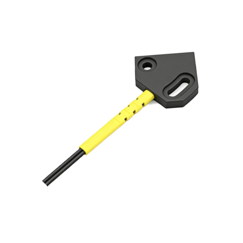
The retro-reflector is not a passive component. Its schematic representation reminds the designer that it is an essential part of the detection loop. Composed of many small cube-corner prisms or specialized lens arrays, it ensures the light is returned precisely. In the schematic's functional flow, its placement defines the effective sensing range and beam alignment. Any object interrupting the path between the sensor and the reflector breaks this return beam, triggering a state change in the sensor's output. The schematic must account for the reflector's specified effective area and return efficiency.
Output Circuitry and Load Interface
Following signal processing, the schematic shows the output stage. Common configurations include NPN (sinking) or PNP (sourcing) transistor outputs, and analog or relay outputs. In a typical NPN schematic, the output transistor's collector is connected to the load, and the emitter to ground (0V). When an object is detected (beam broken), the transistor switches ON, allowing current to sink from the load (e.g., a PLC input, relay coil) through the sensor to ground, completing the circuit. Protection components like flyback diodes for inductive loads or series resistors are often included in application notes adjacent to the schematic.
Practical Considerations from the Schematic
A well-drawn schematic provides insights beyond connectivity. It indicates the need for polarity protection, often with a diode in the power line. It shows test points for troubleshooting, such as a stability LED indicator. The schematic emphasizes the importance of the synchronization between the emitter's modulation frequency and the receiver's demodulation filter. It also implicitly warns against optical interference by showing the direct path to the reflector, guiding the installer to avoid highly reflective backgrounds or obstructions that could create a false return path, bypassing the intended reflector.
Advantages and Typical Applications
The schematic simplicity translates to operational advantages. Compared to through-beam sensors, it requires wiring only to one point (the sensor), reducing installation cost and complexity. The single-unit design offers easier alignment. From the schematic's range specifications, one can deduce its suitability for applications detecting opaque objects on conveyors, pallet positioning, door and gate control, and robotic cell entry/exit monitoring. The modulated light principle, clear from the oscillator in the schematic, makes it robust for use in environments with variable ambient light.
Conclusion and Integration
In summary, the schematic diagram of a retro-reflective photoelectric sensor maps the journey of a modulated light beam from emission to reception. It is a blueprint that explains not just electrical connections but the core principles of modulated light sensing, noise rejection, and reliable switching. For an automation engineer, interpreting this schematic is key to proper sensor selection, correct system integration, effective troubleshooting, and ensuring a robust, fail-safe detection solution in diverse industrial environments. The diagram encapsulates the elegance of a system where light, electronics, and specialized optics combine to perform a critical automation task.