Introduction to Loop Line Inductive Photoelectric Sensors
Loop line inductive photoelectric sensors represent a sophisticated fusion of inductive proximity and photoelectric sensing technologies, designed for high-reliability detection in demanding industrial environments. Unlike standard sensors, these devices are specifically engineered for applications involving continuous material flow on conveyor systems, such as detecting the presence, absence, or precise position of metallic objects within a defined loop or line. Their core function is to provide non-contact, wear-free monitoring, which is critical for maintaining efficiency in automated production and packaging lines. The integration of inductive and photoelectric principles allows these sensors to overcome limitations posed by environmental factors like dust, moisture, or varying surface properties of target objects, ensuring consistent performance where other sensor types might fail.
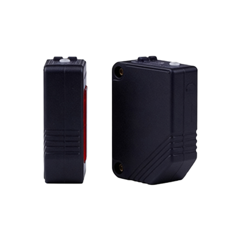
Fundamental Working Principle of the Inductive Component
At the heart of the sensor lies its inductive proximity element. This component operates on the principle of electromagnetic induction. An internal oscillator generates a high-frequency alternating magnetic field that emanates from the sensor's active face. When a metallic target object enters this field, eddy currents are induced on the surface of the metal. These eddy currents draw energy from the oscillator circuit, causing a measurable change in its amplitude or frequency. This change is detected by a threshold circuit within the sensor. For a loop line configuration, this inductive element is often tuned to detect metallic components or tags on products or carriers moving along a predefined path, providing a robust signal that is largely immune to non-metallic contaminants.
Integration with Photoelectric Sensing Technology
The photoelectric component adds a layer of precision and versatility. Typically, this involves a through-beam or retro-reflective photoelectric system aligned with the inductive detection zone. A light emitter, usually an infrared LED, projects a beam of light. A receiver detects the presence or interruption of this beam. In a loop line sensor, this optical path is strategically placed to verify the detection event initiated by the inductive element or to detect non-metallic objects. The key integration lies in the sensor's logic circuitry, which processes signals from both the inductive and photoelectric elements. This allows for complex logic functions, such as requiring both a metallic presence (inductive signal) and a specific physical profile (photoelectric beam break) to register a valid detection, drastically reducing false triggers.
Signal Processing and Output Logic
The raw signals from the inductive coil and photoelectric receiver are fed into a microprocessor or dedicated logic circuit. This unit performs critical signal conditioning, filtering out electrical noise and environmental interference. It then executes a predefined logic operation. Common modes include AND logic, where an output is only activated when both the inductive and photoelectric sensors are triggered simultaneously, and OR logic, where activation from either sensor generates an output. Some advanced models offer programmable logic, allowing engineers to configure custom detection sequences. The processed result controls the sensor's output switch, which is typically a solid-state PNP/NPN transistor or a relay contact, providing a clear digital signal (ON/OFF) to the Programmable Logic Controller (PLC) or machine control system.
Key Design Features for Loop Line Applications
Designing sensors for loop line applications necessitates specific features. The sensing face is often elongated or configured in a channel shape to create a "loop" or "line" detection zone, ensuring objects are detected regardless of their precise lateral position within the track. Housing is robust, rated at IP67 or higher, to withstand washdowns, coolant, and oil ingress. The sensing range and frequency response are calibrated for high-speed production lines, with quick response times to detect rapidly moving objects. Many models incorporate status indicators (LEDs) for power, output, and stability, facilitating easy installation and troubleshooting. The alignment of the photoelectric beam is precisely fixed during manufacturing to ensure long-term stability and eliminate the need for field adjustment.
Typical Industrial Applications and Benefits
These sensors are indispensable in automotive assembly for verifying the presence of engine blocks on pallets, in packaging lines to detect metallic seals on bottles, and in material handling to count metallic parts on conveyors. Their primary benefit is enhanced reliability; the dual-technology approach provides redundancy and verification, minimizing misdetections that can cause costly production stoppages. They offer excellent resistance to environmental challenges like dust, steam, and vibration. By providing accurate position feedback, they enable precise control of robotic arms, sorting gates, and assembly stations, directly contributing to improved product quality, reduced waste, and higher overall equipment effectiveness (OEE) in fully automated industrial systems.