Understanding Photoelectric Sensor Types
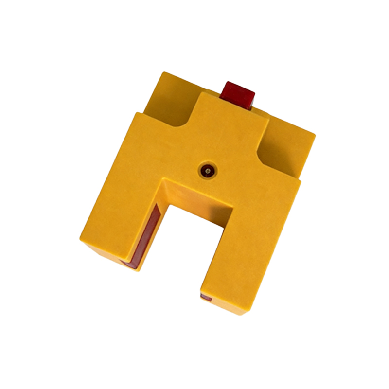
Before beginning any wiring process, it is crucial to identify the specific type of photoelectric sensor being used. The three primary categories are through-beam, retro-reflective, and diffuse reflective sensors. Through-beam sensors consist of separate emitter and receiver units, requiring alignment across the detection path. Retro-reflective models use a single housing containing both emitter and receiver, designed to bounce light off a reflector. Diffuse reflective sensors detect objects by measuring light reflected directly from the target surface. Each type has distinct wiring requirements based on its operating principle and output configuration. Additionally, sensors are classified by output type: NPN (sinking) or PNP (sourcing), which determines how the sensor interfaces with the control system. Always refer to the manufacturer's datasheet for exact specifications, as incorrect identification can lead to wiring errors or device damage.
Pre-Wiring Safety and Preparation
Safety is paramount when working with electrical components. Begin by disconnecting all power sources to the installation area. Use a voltage tester to confirm that circuits are de-energized. Gather necessary tools, including wire strippers, screwdrivers, and appropriate gauges of shielded cable to minimize electrical noise interference. Ensure the sensor's operating voltage range matches the power supply—commonly 10-30 V DC for industrial sensors. Check environmental factors such as temperature, humidity, and potential exposure to chemicals, selecting sensors with suitable ingress protection (IP) ratings if needed. Plan the cable routing to avoid sharp bends, excessive tension, or proximity to high-voltage lines, which can induce false signals. Proper preparation reduces risks and ensures a reliable installation.
Wiring Connections and Diagrams
Most photoelectric sensors feature a standardized color-coded cable or terminal block. For a typical three-wire DC sensor, the connections are: brown wire to positive voltage (+V), blue wire to common negative (0V), and black wire as the output signal. For four-wire models, an additional white wire often provides a second output or function. When wiring, first connect the power leads to the designated power supply terminals. For NPN sensors, the output (black wire) connects to the load, which is then linked to positive voltage; for PNP sensors, the output connects to the load, which then links to common negative. Always use crimp terminals or soldered connections to secure wires, avoiding loose strands that could cause short circuits. Refer to the sensor's wiring diagram, usually printed on the housing or in the manual, for specific details.
Configuring Output and Sensitivity
After wiring, configure the sensor's output mode and sensitivity settings. Many sensors include a rotary potentiometer or digital interface for adjusting sensitivity, which controls the detection range and threshold. Turn on the power and observe the sensor's indicator LED. For through-beam and retro-reflective types, align the emitter and receiver (or reflector) until the LED signals a stable reception. For diffuse sensors, place a target object at the desired detection distance and adjust sensitivity until the LED toggles reliably. Some advanced sensors offer selectable output modes, such as light-on or dark-on operation, which define whether the output activates when light is received or blocked. Use a small screwdriver to make precise adjustments, testing repeatedly with the actual target objects to ensure consistent performance.
Testing and Troubleshooting
Once wired and configured, conduct thorough testing. Introduce target objects into the detection zone and verify the output response using a multimeter or PLC input indicator. Check for false triggers caused by ambient light, reflective surfaces, or vibration. If the sensor fails to operate, systematically troubleshoot: confirm power supply voltage, inspect wiring for loose or reversed connections, and ensure the load (e.g., PLC, relay) is compatible with the sensor's output current. For intermittent issues, consider environmental factors like dust, fog, or electrical noise, and implement solutions such as mounting shields or using filters. Document the installation settings for future maintenance. Regular testing ensures long-term reliability and minimizes downtime in industrial applications.
Integration with Control Systems
Photoelectric sensors are typically integrated into broader control systems, such as programmable logic controllers (PLCs) or robotic controllers. When connecting to a PLC, match the sensor's output type (NPN/PNP) to the PLC input module's specifications. For example, a sinking (NPN) sensor output should connect to a sinking PLC input. Use interface relays if voltage or current ratings differ. In networked systems, follow protocols like IO-Link for digital communication, which allows parameter adjustment and diagnostics via software. Ensure proper grounding of all components to prevent ground loops and electrical interference. Label all wires and document connections in system schematics to facilitate troubleshooting and future expansions. Effective integration optimizes automation processes and enhances system coordination.
Maintenance and Best Practices
To maintain optimal performance, establish a routine maintenance schedule. Periodically clean the sensor lens with a soft, lint-free cloth to remove dust, oil, or debris that could attenuate the light beam. Inspect cables and connections for wear, corrosion, or damage, especially in harsh environments. Verify alignment and sensitivity settings during routine checks, as vibrations or temperature shifts may cause drift. Keep spare sensors on hand for critical applications to reduce replacement time. Adhere to best practices such as using conduit for cable protection, implementing surge protection in areas with power fluctuations, and training personnel on proper handling procedures. Proactive maintenance extends sensor lifespan and ensures consistent operation in demanding industrial settings.