Understanding the Role of Photoelectric Sensors in Dynamic Balancing
In the realm of precision engineering and industrial maintenance, dynamic balancing is a critical process for rotating machinery such as turbines, fans, and motor rotors. The core objective is to measure and correct mass distribution to minimize vibration, reduce wear, and extend operational life. At the heart of this measurement system lies the photoelectric sensor, often referred to as a keyphasor or tachometer sensor. Its primary function is not to measure vibration directly, but to provide a precise timing reference point—a single pulse per revolution. This pulse establishes the phase relationship between the rotational speed and the vibration data captured by proximity probes. Essentially, it tells the balancing analyzer "where" on the rotating shaft the unbalance is occurring. Without this accurate phase reference, determining the correct location and magnitude of balance weights would be impossible, rendering the balancing process ineffective.
Core Components and Sensor Selection Criteria
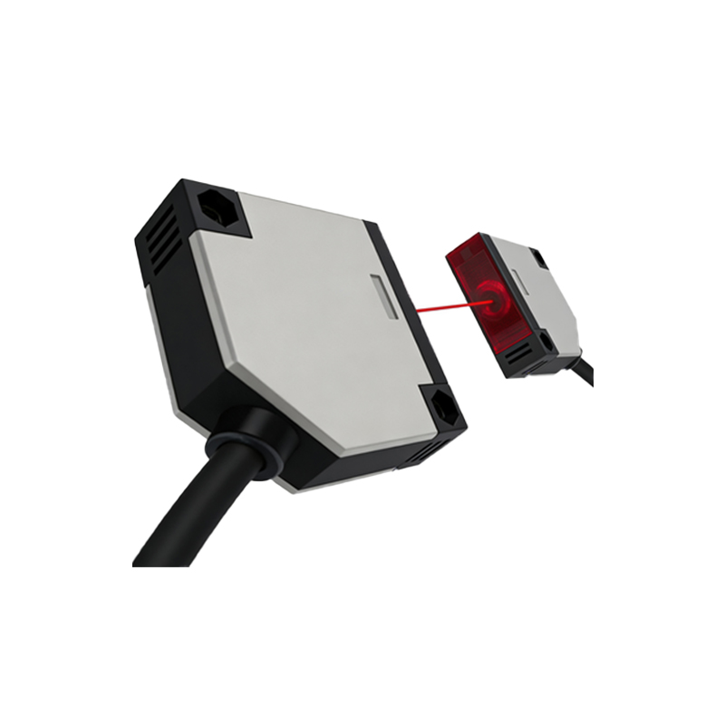
A typical dynamic balancing setup utilizing a photoelectric sensor consists of three main components: the sensor itself, a reflective marker (often a piece of retro-reflective tape), and the balancing analyzer or data acquisition system. The sensor operates on the principle of emitting a beam of light, typically infrared or laser, and detecting its reflection. When the reflective tape passes through the beam, a sharp change in the received light intensity triggers an electrical pulse. Selecting the appropriate sensor is paramount. Key criteria include sensing distance, response time, light source type, and environmental robustness. For high-speed applications, a sensor with a very fast response time (microseconds) is essential to avoid pulse distortion. The sensing distance must be compatible with the installation setup, ensuring reliable detection without physical contact. Furthermore, sensors must be chosen to withstand ambient conditions like oil mist, dust, and temperature fluctuations common in industrial environments.
Standard Wiring Configuration and Pinout Details
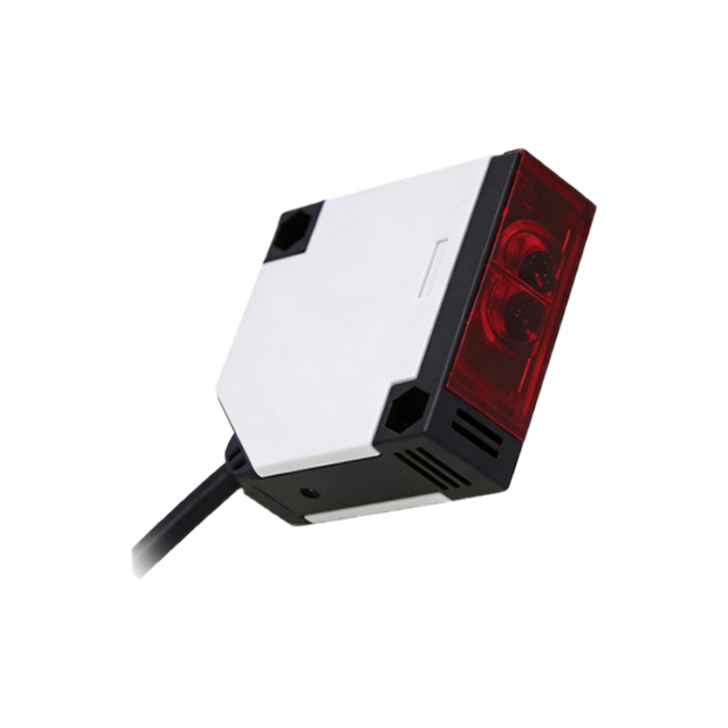
Correct wiring is fundamental to signal integrity and system safety. Most industrial photoelectric sensors for dynamic balancing come in a three-wire DC configuration, which is the industry standard. The wiring typically follows this scheme: A brown wire is connected to the positive DC supply voltage (commonly +12V or +24V DC). A blue wire is connected to the DC common or ground (0V). A black wire is the switched output signal line. This output is usually configured as an NPN (sinking) or PNP (sourcing) transistor. For compatibility with most balancing analyzers, an NPN open-collector output is frequently used. In this setup, the black wire provides a path to ground (0V) when the sensor is active (tape detected), creating a falling-edge pulse. The analyzer's input channel is pulled up to the supply voltage internally or via an external resistor. It is crucial to verify the sensor's datasheet and the analyzer's input requirements to match the output type (NPN/PNP) and voltage levels precisely. Incorrect matching can lead to no signal, weak signal, or potential damage.
Step-by-Step Installation and Alignment Procedure
Proper physical installation ensures consistent and reliable pulse generation. Begin by securely mounting the sensor on a stable bracket, ensuring it is vibration-isolated from the machine itself. The sensor should be positioned so its beam is perpendicular to the shaft surface. The critical step is applying the reflective marker. Use high-quality, clean retro-reflective tape. A single piece, approximately 1-inch square, is sufficient. Ensure the shaft surface at the tape location is clean, dry, and free of rust or oil. The tape must be applied smoothly without wrinkles or air bubbles. The alignment process involves powering the sensor and using its built-in indicator LED (if available) or a multimeter. Adjust the sensor's distance and angle until the indicator shows a stable "on" state when the tape is in the beam and a stable "off" state otherwise. The goal is to achieve a clean, high-contrast signal transition. For optimal results, the tape should be the only highly reflective surface in the sensor's field of view to prevent false triggering.
Signal Conditioning and Integration with the Balancing Analyzer
The raw pulse from the sensor often requires conditioning before being processed by the balancing analyzer. While modern sensors have clean outputs, long cable runs or electrically noisy environments can introduce interference. Using shielded cable is non-negotiable. The cable shield should be grounded at only one end, typically at the analyzer chassis, to prevent ground loops. The signal wire (black) and the DC supply wires (brown, blue) should be routed separately from high-power AC lines. The balancing analyzer's input channel for the photoelectric sensor is usually labeled "Keyphasor," "Tacho," or "RPM." Connect the sensor's output (black wire) to this input terminal and the sensor's ground (blue wire) to the analyzer's common ground. Upon connection, initiate the analyzer's setup menu to configure the input for the correct trigger type (typically falling edge for NPN). The analyzer should then display a stable RPM reading and a clear, jitter-free phase angle. A clean, square-wave pulse on an oscilloscope is the best verification of a properly conditioned signal.
Troubleshooting Common Wiring and Signal Issues
Even with careful installation, issues can arise. A systematic approach to troubleshooting is essential. The most common problem is "no signal." First, verify power: check for correct DC voltage (e.g., 24V) between the brown (+) and blue (-) wires at the sensor connector. Next, check the sensor's operation: observe its status LED while manually passing the reflective tape. If the LED responds but the analyzer does not, the issue is likely in the wiring or analyzer configuration. Check continuity and for short circuits in the cable. Ensure the analyzer input is correctly configured for NPN/PNP. Another frequent issue is "unstable RPM" or "phase jitter." This is often caused by a poor reflective target (dirty, damaged, or substandard tape), inadequate sensor alignment, or electrical noise. Re-apply the tape, re-align the sensor meticulously, and verify cable shielding. In high-electrical-noise environments, adding a ferrite bead near the analyzer input or using a signal conditioner module may be necessary to clean the pulse.
Best Practices for Long-Term Reliability and Safety
Ensuring the long-term reliability of the photoelectric sensor system involves adherence to best practices. Use only industrial-grade sensors and components rated for the specific environment. Implement strain relief on all cable connections to prevent wire breakage from vibration. Establish a regular maintenance schedule to inspect the reflective tape for wear, dirt, or peeling, and clean the sensor's lens if necessary. Document the wiring diagram, sensor part number, and alignment settings for future reference. From a safety perspective, always follow lockout-tagout (LOTO) procedures before working on or near the machinery. Ensure all wiring conforms to local electrical codes and standards. Never run sensor cables in the same conduit as power cables. By meticulously following these wiring, installation, and maintenance protocols, electrical engineers can guarantee that the photoelectric sensor provides a flawless timing reference