Understanding Switching Frequency in Proximity Sensors
The switching frequency of a proximity sensor, often expressed in Hertz (Hz), is a critical parameter defining the maximum number of on/off switching cycles the device can perform per second. It fundamentally determines the sensor's response speed and its suitability for high-speed applications. A higher switching frequency allows the sensor to detect objects moving past it at greater velocities or to respond to rapid changes in target position. However, this capability is not without trade-offs. Factors such as sensor technology (inductive, capacitive, photoelectric), sensing distance, target material and size, and environmental conditions all interplay to influence the achievable and reliable switching frequency. Setting this parameter correctly is not merely a technical adjustment; it is a core aspect of system integration that directly impacts production throughput, machine reliability, and process control accuracy.
Key Factors Influencing Adjustable Frequency
Before attempting to adjust the frequency, one must understand the variables that constrain it. For inductive sensors, the oscillation circuit's design and the damping characteristics when a metallic target enters the field are primary determinants. The size and material of the target are paramount; a larger, ferrous target (like steel) provides stronger damping, potentially allowing for stable operation at higher frequencies compared to a small or non-ferrous target (like aluminum or brass). The rated operating distance also plays a role; a sensor used well within its nominal range will typically perform more robustly than one operating at its limit. For capacitive and photoelectric sensors, similar principles apply but with different physical interactions. Environmental electrical noise can also induce false switching, effectively limiting the usable frequency in noisy industrial settings.
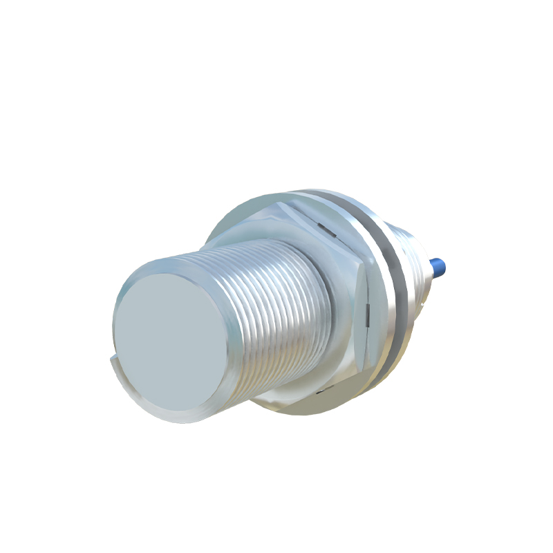
Step-by-Step Guide to Frequency Adjustment
Many modern programmable proximity sensors offer adjustable switching frequency settings, usually accessible via a teach-in button, potentiometer, or software interface. The first step is always to consult the specific sensor's datasheet and operational manual. Typically, the adjustment involves selecting between two or more preset frequency ranges, such as a "High-Speed" mode (e.g., 1.5 kHz) and a "Standard" or "Noise-Immune" mode (e.g., 100 Hz). To adjust, power the sensor and ensure it is in a non-active state (no target present). Activate the programming mode as per instructions—this might involve holding a button for several seconds until an LED indicator changes pattern. Then, select the desired frequency setting. After configuration, it is imperative to validate the setting by testing with the actual target under real operating conditions, including the expected speed and repetition.
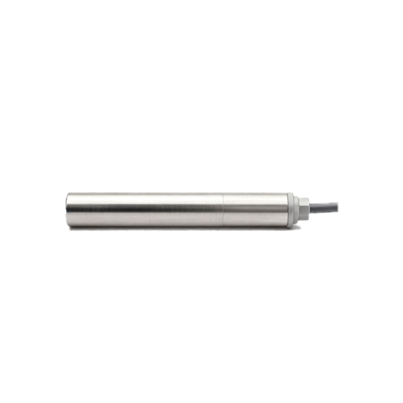
Optimizing for High-Speed Applications
For applications involving fast-moving parts on conveyors, sorting systems, or high-speed packaging machinery, maximizing the switching frequency is often the goal. To achieve this, start by selecting a sensor specifically designed for high-frequency operation. Ensure the target is optimal: use a standard test target as specified by the sensor manufacturer (usually a square of mild steel) that is larger than the sensor's active face. Minimize the sensing gap; operate the sensor as close to the target as possible while maintaining a reliable margin. Shielding the sensor cable and using twisted-pair, shielded cables with proper grounding is non-negotiable to mitigate electromagnetic interference, which can cause erratic behavior at high frequencies. Finally, verify that the connected load (PLC input, relay) can also handle the high-speed switching signals.
Mitigating Noise and Ensuring Stability
In electrically noisy environments—near variable frequency drives (VFDs), welding equipment, or large motors—a high switching frequency setting can make the sensor more susceptible to interference. If instability or false triggers are observed, reducing the switching frequency is a primary corrective action. Lower frequency settings often incorporate internal filtering algorithms that increase noise immunity. Additionally, employ robust installation practices: use metal conduit for cabling, ensure solid earth grounding for both the sensor and the metal mounting bracket, and maintain maximum practical distance from noise sources. For critical applications, sensors with built-in diagnostics or short-circuit protection offer an added layer of reliability. The trade-off here is response speed for operational stability.
Verification and Best Practices
After any adjustment, thorough verification is essential. Use an oscilloscope to monitor the sensor's output signal in relation to the target's position. This will reveal the true response time, switch-on/switch-off delays, and any signal bounce or noise. For repetitive processes, run a prolonged test cycle at the maximum expected production speed to ensure no missed counts or double counts. Document the settings for each sensor within the machine documentation. As a best practice, always procure sensors with a frequency specification that exceeds your application's theoretical requirement by a safe margin (e.g., 20-30