Introduction to Photoelectric Sensors
Photoelectric sensors are widely used in industrial automation for detecting objects, measuring distances, and calculating speed. These sensors operate by emitting a light beam—typically infrared, visible, or laser—and detecting changes in the received light caused by an object interrupting or reflecting the beam. Their non-contact nature makes them ideal for applications involving fast-moving or delicate items, such as in conveyor systems, packaging machinery, and automotive assembly lines. Understanding how to leverage photoelectric sensors for speed calculation requires a grasp of their working principles, which include through-beam, retro-reflective, and diffuse reflective modes. Each mode offers distinct advantages depending on the environment and object properties, ensuring accurate data collection for subsequent speed computations.
Fundamentals of Speed Calculation
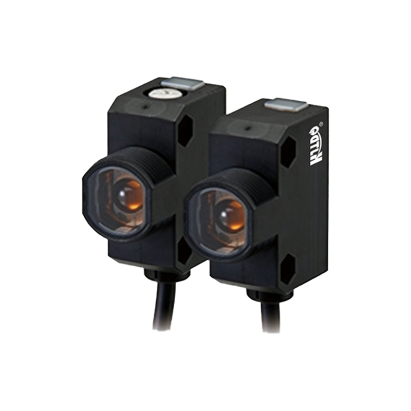
Speed calculation using photoelectric sensors relies on basic physics principles, where speed is defined as the distance traveled per unit of time. In practice, this involves measuring the time interval between sensor triggers as an object passes through the detection zone. For instance, if a sensor detects an object at two known points along a path, the distance between those points divided by the time elapsed yields the object's speed. This method is straightforward but requires precise sensor placement and timing accuracy. Factors like object size, sensor response time, and environmental conditions (e.g., ambient light or dust) can influence measurements, so calibration and error mitigation are essential for reliable results.
Setting Up the Sensor System
To calculate speed effectively, proper sensor installation is critical. Begin by selecting an appropriate photoelectric sensor type based on the application. Through-beam sensors, with separate emitter and receiver units, are often preferred for speed measurement due to their high accuracy and long detection ranges. Position the sensors at fixed intervals along the object's path, ensuring they are aligned perpendicularly to minimize detection errors. Connect the sensors to a programmable logic controller (PLC) or data acquisition system that records trigger timestamps. Calibrate the system by measuring the exact distance between sensor points using tools like calipers or laser rangefinders, and test with known speeds to verify accuracy before deployment in operational environments.
Mathematical Formulas and Examples
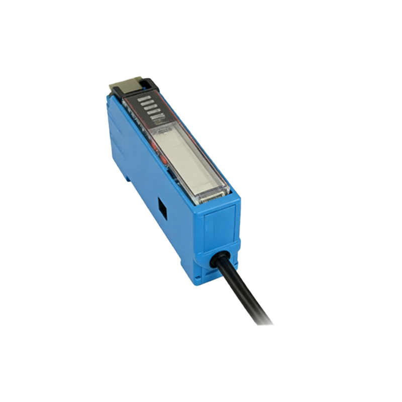
The core formula for speed calculation is: Speed (v) = Distance (d) / Time (t). Here, distance refers to the separation between sensor detection points, and time is the interval between consecutive sensor triggers. For example, if two photoelectric sensors are placed 0.5 meters apart on a conveyor belt, and an object triggers the first sensor at t=0 seconds and the second at t=0.25 seconds, the speed is calculated as v = 0.5 m / 0.25 s = 2 m/s. In cases where multiple objects or continuous motion are involved, advanced methods like using encoder-based sensors or frequency analysis may be applied. Always account for unit consistency (e.g., meters per second or kilometers per hour) to avoid calculation errors in reporting or system integration.
Data Processing and Error Correction
Raw sensor data often contains noise or inaccuracies that can skew speed calculations. Implement signal conditioning techniques, such as filtering algorithms in the PLC, to smooth out erratic triggers caused by vibration or partial object detection. For high-precision applications, use sensors with fast response times (e.g., microseconds) and average multiple measurements to reduce random errors. Additionally, consider environmental adjustments—like shielding sensors from ambient light or using polarized lenses to prevent false triggers from reflective surfaces. Regular maintenance, including lens cleaning and alignment checks, helps sustain measurement integrity over time, ensuring consistent speed data for process control and monitoring.
Practical Applications in Industry
Photoelectric sensors for speed calculation are integral to various industrial processes. In manufacturing, they monitor conveyor belt speeds to optimize production rates and prevent bottlenecks. In automotive testing, they measure vehicle speed on dynos or track systems by detecting wheel rotations. Robotics applications use these sensors to control arm movement speeds for precision tasks. Each scenario may require tailored setups; for instance, retro-reflective sensors might be used in confined spaces, while diffuse sensors suit irregularly shaped objects. By integrating speed data with automation systems, industries can enhance efficiency, reduce downtime, and improve safety through real-time adjustments based on accurate velocity feedback.
Conclusion and Best Practices
Calculating speed with photoelectric sensors is a reliable method when executed with attention to detail. Key best practices include selecting the right sensor type, ensuring precise installation and calibration, and applying robust data processing to minimize errors. Always validate calculations against known standards and update system parameters as environmental or operational conditions change. As technology advances, newer sensors with enhanced features like digital outputs or IoT connectivity offer even greater precision and ease of integration. By mastering these fundamentals, engineers can leverage photoelectric sensors to achieve accurate speed measurements, driving improvements in automation and operational performance across diverse industrial settings.