Understanding Proximity Sensor Module Components
Proximity sensor modules are integral to modern industrial automation, enabling non-contact detection of objects. A typical module consists of a sensor head, an amplifier or conditioning circuit, and output terminals. The sensor head, often based on inductive, capacitive, or photoelectric principles, generates a signal when an object enters its sensing range. This signal is processed by the amplifier, which converts it into a usable output, such as a digital switch signal or analog voltage. Key terminals include power supply (Vcc and GND), output signal (OUT), and sometimes auxiliary connections for diagnostics or configuration. Understanding these components is crucial before proceeding with wiring, as incorrect connections can lead to module failure or system malfunctions.
Power Supply Wiring Considerations
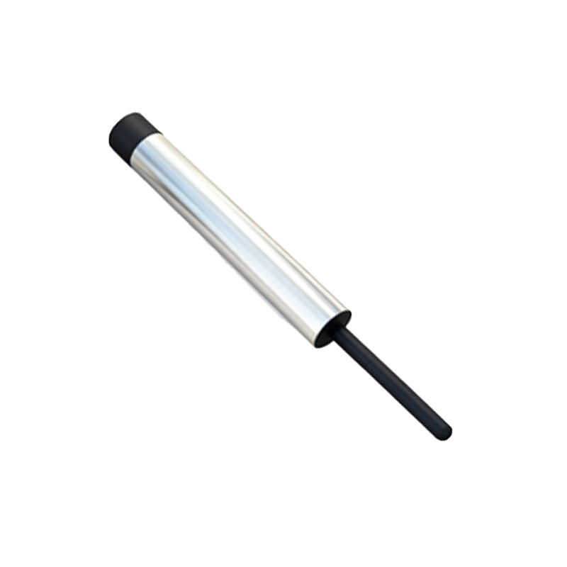
Proper power supply connection is fundamental for reliable operation. Most industrial proximity sensor modules operate on DC voltages, commonly 12V DC or 24V DC, though some support AC power. Always verify the voltage rating on the module's datasheet. Connect the positive lead (Vcc) to the designated positive terminal and the negative lead (GND) to the ground terminal. Use shielded cables in electrically noisy environments to prevent interference. Ensure the power source provides stable voltage within the specified tolerance; fluctuations can affect sensing accuracy. Incorporate a fuse or circuit breaker in the supply line for overcurrent protection. For modules with multiple power options, select the appropriate setting via internal jumpers or external switches as per the manual.
Output Signal Connection Methods
The output terminal (OUT) interfaces with control systems like PLCs, relays, or microcontrollers. Modules typically offer digital outputs (NPN or PNP transistor-based) or analog outputs (0-10V, 4-20mA). For NPN outputs, the OUT terminal acts as a sinking output, connecting to the load's positive side, while the load's negative side ties to ground. PNP outputs are sourcing, with OUT connected to the load's negative side and the positive side to Vcc. Analog outputs require connection to analog input modules, with careful attention to impedance matching. Always confirm the output type and wiring diagram provided by the manufacturer. Use twisted-pair cables for analog signals to minimize noise, and ensure proper grounding to avoid ground loops that could distort readings.
Wiring for Different Sensor Types
Inductive proximity sensors, used for metal detection, typically have three wires: brown (Vcc), blue (GND), and black (OUT). Capacitive sensors, suitable for non-metallic materials, follow similar wiring but may include a sensitivity adjustment wire. Photoelectric sensors often have additional wires for light-on/dark-on mode selection or timer functions. Two-wire AC sensors integrate power and output in a single loop, simplifying installation but requiring careful load matching. When wiring multiple sensors, avoid parallel connections that can cause cross-talk; instead, use separate cables or shielded conduits. Label each wire clearly according to the color code or terminal markings to prevent errors during maintenance or troubleshooting.
Installation and Environmental Factors
Mount the sensor module securely, ensuring the sensing face is unobstructed and aligned correctly with the target. Maintain the specified sensing distance, as deviations can reduce performance. In harsh environments—such as those with high temperatures, humidity, or vibration—use IP-rated enclosures or conformal coating to protect the wiring connections. Keep wiring away from high-voltage lines or motors to prevent electromagnetic interference. For long cable runs, consider voltage drop by using thicker gauge wires, especially for analog outputs where signal integrity is critical. Regularly inspect connections for corrosion or loosening, which can lead to intermittent faults. Follow local electrical codes and safety standards, such as NEC or IEC guidelines, for industrial installations.
Troubleshooting Common Wiring Issues
If a sensor module fails to operate, first check power supply connections with a multimeter to confirm voltage levels. Verify that the output load (e.g., PLC input) is compatible with the sensor's output characteristics. Loose or reversed wires are a frequent cause of malfunction; re-examine terminal screws and polarity. In noisy settings, interference may cause false triggering—adding ferrite cores or relocating cables can mitigate this. For analog sensors, calibrate zero and span settings after wiring to ensure accurate readings. Consult the module's diagnostic indicators, such as LED status lights, which often signal wiring errors like short circuits or open loads. Document the wiring scheme for future reference, as this aids in rapid fault identification and repair.