Understanding Proximity Sensor Fundamentals
Proximity sensors are indispensable components in modern industrial automation, providing non-contact detection of metallic or non-metallic objects. Their operation hinges on generating an electromagnetic field or beam of radiation. When a target enters this field, it causes a change in the sensor's state, which is then converted into an electrical signal. The core types include inductive (for metals), capacitive (for various materials including liquids), and photoelectric sensors. A proper grasp of their working principle is the first step toward correct installation and wiring, ensuring reliable performance in demanding environments such as assembly lines, packaging machinery, and robotic systems. The choice of sensor directly influences the subsequent wiring configuration.
Key Wiring Configurations: 2-Wire, 3-Wire, and 4-Wire
The wiring methodology is primarily defined by the number of connecting wires. The 2-wire sensor is the simplest, acting like a switch in series with the load and power supply. It is easy to install but has limitations regarding residual current and voltage drop. The 3-wire sensor is the most common in DC systems, featuring separate wires for power supply positive, power supply negative (common), and the output signal. This design offers stable performance and minimal leakage current. There are two main output types: PNP (sourcing) and NPN (sinking), which determine the current flow direction. The 4-wire sensor typically incorporates two separate outputs (e.g., one PNP and one NPN) or includes additional diagnostic or enable/disable functions, providing greater flexibility for complex control logic.
Detailed Guide to 3-Wire DC Sensor Wiring (PNP vs. NPN)
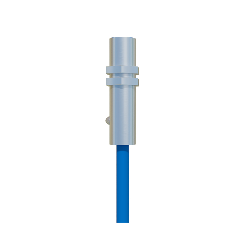
Correctly identifying and connecting 3-wire sensors is critical. A PNP (Positive-Negative-Positive) sensor switches the positive voltage to the load. Its wiring is as follows: the brown wire (usually) connects to the DC positive supply (+V), the blue wire to the DC negative or common (0V), and the black wire is the output that provides +V to the load when activated. The load's other terminal connects to 0V. Conversely, an NPN (Negative-Positive-Negative) sensor switches the negative or ground path. Here, the brown wire connects to +V, the blue to 0V, and the black output wire connects to the load. The load's other side is then connected to +V. When activated, the NPN output connects the load to 0V, completing the circuit. Misconfiguration can lead to short circuits or non-operation.
Wiring for AC Powered Proximity Sensors
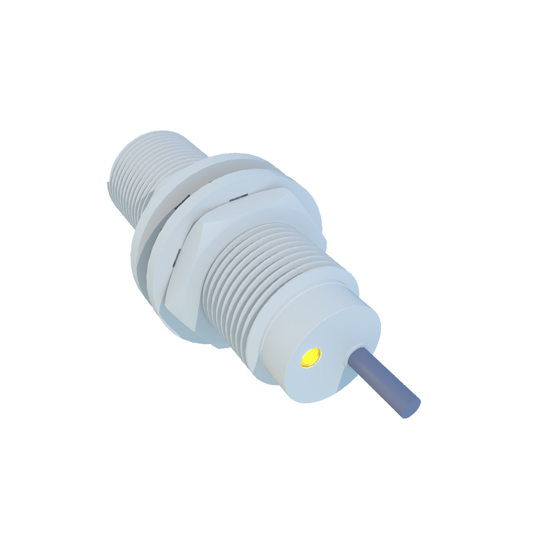
AC-powered proximity sensors, often 2-wire or sometimes 3-wire, are used with alternating current supplies, commonly 120VAC or 240VAC. A 2-wire AC sensor is connected in series with the load and the AC power source. It is crucial to observe the load current limits to ensure proper switching. A 3-wire AC sensor will have separate lines for AC live, AC neutral, and the output switch. The output is typically a solid-state relay (SSR) that can control an AC or DC load independently. Proper grounding and the use of conduit for wire protection are essential safety practices when dealing with higher AC voltages to prevent electrical hazards and ensure equipment longevity.
Shielded Cabling and Noise Immunity Practices
In industrial settings, electrical noise from motors, variable frequency drives (VFDs), and power lines can interfere with sensor signals, causing erratic operation. Using shielded cables is a highly effective countermeasure. The cable's metallic shield should be grounded at only one end, typically at the control panel end, to prevent ground loops. Wires should be routed away from high-power cables; crossing them at a 90-degree angle is preferable if separation is not possible. Employing twisted-pair wires for the signal and its return path can also significantly reduce electromagnetic interference (EMI). These practices are non-negotiable for maintaining signal integrity in noisy environments.
Integration with PLCs and Control Systems
The final step is integrating the sensor with a Programmable Logic Controller (PLC) or other control system. For a 3-wire PNP sensor connected to a PLC digital input (sinking type), the sensor's black output wire connects to the PLC input terminal. The PLC input's common is connected to 0V. For an NPN sensor with a PLC digital input (sourcing type), the sensor's black wire connects to the PLC input, and the PLC input's common is connected to +V. Always consult the manuals for both the sensor and the PLC to match the sourcing/s