Understanding Photoelectric Sensor Terminal Functions
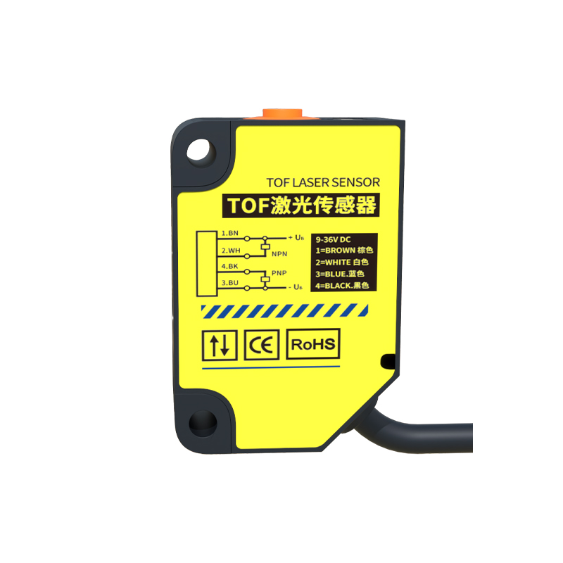
Photoelectric sensors are pivotal in industrial automation for detecting objects, measuring distances, and ensuring process control. Their terminal wiring is fundamental to operational reliability. Typically, these sensors feature three to five terminals, including power supply (V+ and COM), output (NO/NC), and sometimes auxiliary lines for diagnostics or synchronization. The V+ terminal connects to the positive DC voltage (commonly 12-24V DC), while COM is the common ground or negative return. Output terminals provide switching signals—Normally Open (NO) closes the circuit upon detection, and Normally Closed (NC) opens it. Miswiring can lead to sensor failure or system malfunctions, so understanding each terminal's role is crucial for safe installation.
Step-by-Step Wiring Procedures for Common Sensor Types
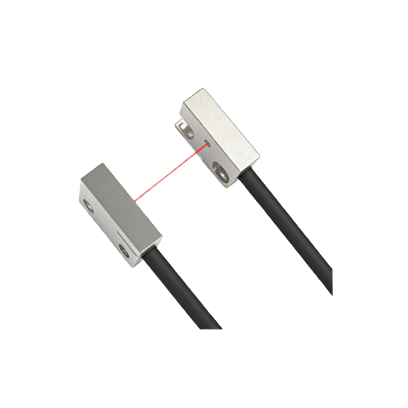
For diffuse, retro-reflective, and through-beam photoelectric sensors, wiring follows a standardized approach. First, ensure the power is off to prevent electrical hazards. Connect the V+ wire (often brown) to the positive DC supply and the COM wire (blue) to the negative side. The output wire (black or white) links to the load, such as a PLC input or relay. In retro-reflective sensors with polarization filters, a separate terminal may exist for synchronization to avoid interference. Always refer to the datasheet for voltage ratings—exceeding these can damage internal circuits. Use shielded cables in high-noise environments to minimize false triggers from electromagnetic interference.
Best Practices for Terminal Connections and Maintenance
Secure terminal connections are vital for long-term performance. Employ crimped or ferruled wires to prevent fraying and ensure tight screw terminals. Avoid loose strands that could cause short circuits. For maintenance, periodically inspect terminals for corrosion or wear, especially in harsh conditions like humidity or dust. Implement strain relief on cables to reduce mechanical stress on terminals. Label wires clearly during installation to simplify troubleshooting. Additionally, test sensor output with a multimeter after wiring to verify signal integrity before integrating into the control system.
Troubleshooting Common Wiring Issues and Errors
Frequent wiring problems include incorrect polarity, loose connections, or ground loops. If a sensor fails to power on, check the V+ and COM connections for proper voltage using a voltmeter. Erratic output might stem from noise—ensure shielded cables are grounded at one end only. For false detections, verify that reflective surfaces aren't interfering with the sensor beam. In daisy-chained setups, confirm load currents don't exceed the sensor's switching capacity. Documenting the wiring diagram aids in rapid fault isolation, reducing downtime in production lines.
Advanced Considerations for Complex Industrial Setups
In advanced applications like multi-sensor networks or high-speed counting, wiring precision becomes critical. Use separate power supplies for sensors and loads to avoid voltage drops. For sensors with analog outputs (e.g., 4-20mA), connect terminals to dedicated analog input modules, ensuring proper scaling. In safety-rated sensors, follow ISO 13849 guidelines for redundant wiring to prevent hazardous failures. Integrate surge protectors on terminals in areas prone to voltage spikes. Regularly update wiring practices based on manufacturer advisories to leverage technological improvements in sensor design.