Understanding Proximity Switch Sensor Basics
Proximity switch sensors are fundamental components in industrial automation, detecting the presence or absence of an object without physical contact. Their operation relies on generating an electromagnetic field. When a metallic target enters this field, it causes a change in the sensor's oscillation amplitude, triggering a switching signal. The core types include inductive (for metals), capacitive (for various materials), and magnetic sensors. Correct directional alignment is not merely about mounting; it is critical for ensuring the sensor's specified sensing range, reliability, and immunity to false triggers. Misalignment can lead to missed detections, premature wear, or damage to the sensor or target, directly impacting production line efficiency and safety.
Pre-Adjustment Preparation and Safety Protocols
Before initiating any adjustment, a thorough preparatory phase is mandatory. First, consult the sensor's datasheet from the manufacturer. This document contains the exact sensing distance (Sn), recommended operating distance, and detailed dimensional drawings specifying the effective sensing face location. Gather necessary tools: a non-metallic adjustment tool (often provided), a multimeter or PLC input indicator to monitor the output signal, and appropriate locknuts or mounting hardware. The paramount rule is to implement Lock-Out Tag-Out (LOTO) procedures. De-energize the entire circuit or machine to prevent accidental actuation. Verify zero energy state before proceeding. Clear the area around the sensor of any debris or metallic objects that could interfere with testing.
Step-by-Step Directional Alignment Procedure
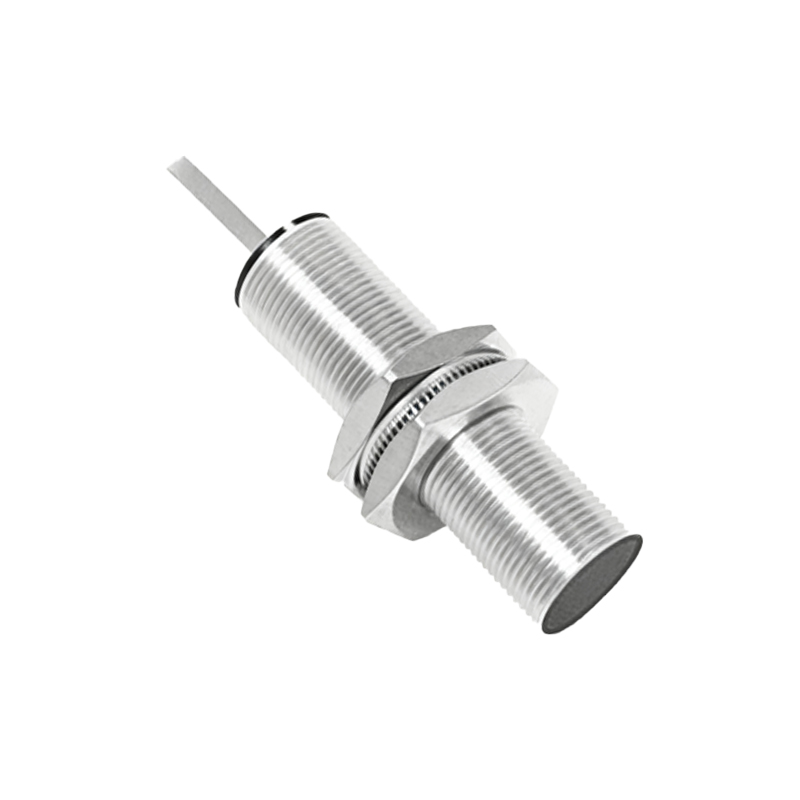
Begin by loosely mounting the sensor in its approximate final location using the bracket or mounting holes. Ensure the target object, typically a metal flag or the machine part itself, is in its "home" or non-detection position. The key principle is to align the sensor's active face perpendicular to the direction of target approach. For a standard cylindrical sensor, the sensing field projects axially from the front face. Slowly bring the target towards the sensor along the intended path of travel. Using the non-metallic tool, carefully rotate the sensor body until the active face is squarely facing the oncoming target. Fine-tune the angle while observing the output signal via your monitoring device. The goal is to achieve a consistent and repeatable switch signal exactly when the target reaches the desired position within the nominal sensing range.
Optimizing Sensing Distance and Hysteresis
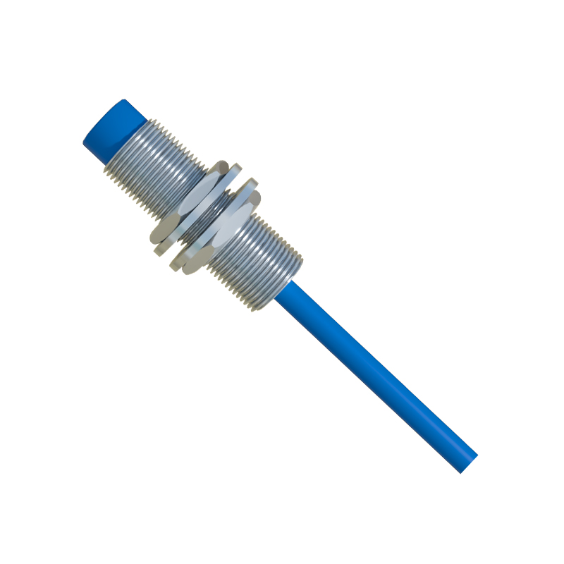
Once directional alignment is achieved, precise adjustment of the sensing distance is next. Most industrial proximity sensors have a built-in potentiometer or teach-in function for this purpose. With the target at the desired actuation point, adjust the potentiometer clockwise until the output LED just triggers (or the signal changes state). Then, slowly retract the target. Note the point where the sensor de-actuates. The difference between the actuate and release points is the hysteresis, a crucial feature preventing signal chatter. Optimize the setting so that the hysteresis provides a stable, bounce-free signal while ensuring the target is reliably detected over its full range of motion, accounting for mechanical tolerances and vibration.

Verification, Testing, and Final Securing
Verification is a multi-step process. Conduct a series of dry runs without activating the main machine drive. Manually cycle the target through its full operational path at varying speeds, including the maximum designed speed. Monitor the sensor output for every cycle; it must be consistent without missed pulses or false triggers. Next, introduce potential interference. Check if adjacent moving metal parts, hydraulic lines, or other sensors affect performance. After successful verification, while maintaining the perfect alignment, securely tighten the mounting locknuts. Avoid over-tightening, as this can distort the housing and affect performance. Finally, re-energize the system and conduct a final operational test under normal power and control logic to confirm seamless integration.
Troubleshooting Common Alignment Issues
Several common issues arise from improper directional adjustment. If the sensor fails to detect, re-check the alignment perpendicularity and ensure the target material is compatible (e.g., using an inductive sensor on non-ferrous metal may require a reduced sensing range). Intermittent detection often points to insufficient hysteresis or a misaligned sensor where the target only partially enters the sensing field. False triggering can be caused by alignment towards unintended metal objects, such as moving machine frames or fasteners. Always use shielded sensors in electrically noisy environments and ensure proper grounding. If problems persist, double-check the power supply voltage and load current against the sensor specifications, as these can influence performance.
Best Practices for Long-Term Reliability
For sustained accuracy, incorporate regular directional checks into the preventive maintenance schedule. Vibration and mechanical shocks can gradually shift sensor alignment. Periodically inspect