Understanding the Retro-Reflective Principle
A retro-reflective photoelectric sensor operates by emitting a light beam towards a specialized reflector. This reflector, typically a corner-cube prism, is designed to return the light beam directly to its source regardless of the angle of incidence. The sensor's receiver detects this returned beam. An object is sensed when it interrupts this beam path between the sensor and the reflector. This design offers a significant advantage over through-beam sensors by requiring wiring and power only on one side of the detection point, simplifying installation in many industrial settings. The key to reliable operation is ensuring a clear, unobstructed path to the reflector and understanding the sensor's polarization filter feature, which is often used to prevent false triggers from shiny surfaces.
Standard Wiring Configurations and Terminals
Most modern retro-reflective sensors come in a pre-wired connector style or with a terminal block. The fundamental terminals are consistent across manufacturers: Brown wire or terminal for DC positive supply voltage (typically +12V to +24V DC), Blue wire or terminal for DC common (0V), and Black wire (or sometimes white) for the output signal. For AC-powered models, Brown is often Live (L) and Blue is Neutral (N). The output type is critical: NPN (sinking) or PNP (sourcing). An NPN output switches the load to common (0V), common in Asia and for PLCs with sinking inputs. A PNP output switches the load to positive voltage, prevalent in Europe and for PLCs with sourcing inputs. Always verify the datasheet for the specific pinout.
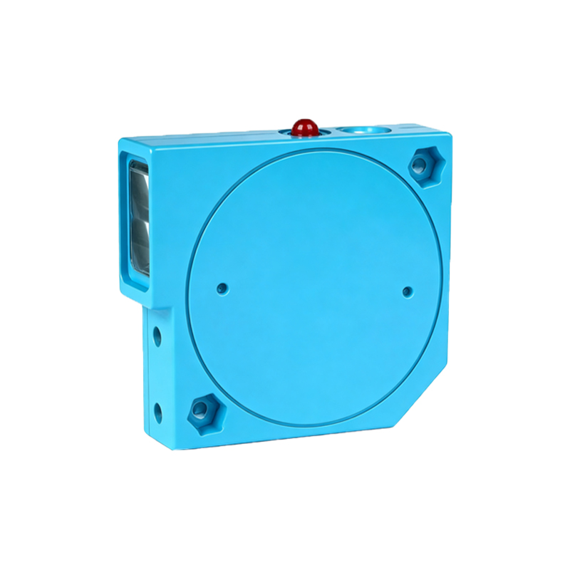
Connecting to a Programmable Logic Controller (PLC)
Integrating a retro-reflective sensor with a PLC is a common task. For a DC PNP sensor, connect the brown wire to the PLC's +24V DC supply, the blue wire to the PLC's 0V (common), and the black output wire to the designated PLC digital input point. The PLC input module itself provides the path to common internally. For an NPN sensor, the wiring changes: brown to +24V, blue to 0V, and the black output wire connects to the PLC input. However, the PLC input's common terminal must be connected to +24V to complete the circuit, as the NPN transistor sinks current. Mismatching NPN/PNP with the PLC input type is a primary cause of malfunction.
Implementing a Standalone Relay Control Circuit
For applications not involving a PLC, such as directly controlling a motor starter coil, solenoid, or indicator lamp, a relay is often used as an intermediary load. Wire the sensor's power supply (brown/blue) as usual. Connect the sensor's output (black) to one side of the relay coil. For a PNP sensor, connect the other side of the relay coil to 0V. When an object is detected, the PNP output energizes, sending +24V to the coil, closing the relay contacts. For an NPN sensor, connect the other side of the relay coil to +24V. The NPN output will sink the current to 0V when active, completing the coil circuit. Always use a flyback diode across the relay coil to suppress voltage spikes.
Wiring Considerations for Enhanced Functionality
Many retro-reflective sensors offer additional wiring options for advanced control. A second output wire (often white) may provide a complementary signal (NO/NC). Timer function models have separate wires for power, output, and timer adjustment. Teach-in or sensitivity adjustment models may have two additional wires for a remote teach button. For synchronous (mutual interference prevention) operation in dense sensor arrays, a synchronization cable must be run between the SYNC terminals of the affected sensors. Always maintain proper cable separation; run sensor cables in separate conduits or trays away from high-voltage power cables to prevent electromagnetic interference (EMI) from inducing false signals.
Troubleshooting Common Wiring and Installation Issues
Persistent problems often trace back to wiring errors. If the sensor's power LED is off, check voltage polarity and magnitude at the sensor terminals. If the power LED is on but the output does not activate, verify the sensing distance and alignment with the reflector; ensure the object fully breaks the beam. For erratic operation, check for environmental factors like dust, steam, or ambient light flooding the receiver. Use an oscilloscope to check for noise on the supply lines. Confirm the load (PLC input, relay coil) impedance is within the sensor's specified range. A load that draws too little current (like a high-impedance PLC input) may not allow the sensor's solid-state output to fully switch on, leading to unreliable operation. Always consult the manufacturer's manual for diagnostic LED patterns.