Understanding Photoelectric Sensor Fundamentals
Photoelectric sensors are critical components in modern automated car wash systems, responsible for detecting vehicle presence, position, and dimensions to ensure precise and safe operation. These sensors typically operate by emitting a light beam—often infrared, laser, or visible LED—and detecting changes in the received light signal caused by an object interrupting or reflecting the beam. The primary types used in car washes include through-beam (opposed), retro-reflective, and diffuse reflective sensors. Through-beam sensors consist of separate emitter and receiver units, offering the longest sensing ranges and highest reliability for detecting vehicles of varying sizes. Retro-reflective types use a reflector to bounce the beam back to a combined emitter/receiver unit, suitable for moderate distances. Diffuse sensors detect light reflected directly from the target vehicle itself, ideal for close-range applications like detecting specific vehicle parts. A fundamental grasp of these operating principles is essential before attempting any diagnostic procedures, as the testing approach varies by sensor type.
Common Symptoms of a Failing Sensor
Identifying a potentially faulty photoelectric sensor begins with recognizing abnormal system behaviors. In a car wash, frequent and unexplained stoppages during the wash cycle are a primary indicator. The system may halt as if no vehicle is present, or it might fail to initiate a cycle despite a vehicle being correctly positioned. Erratic equipment movement is another red flag; for instance, brushes or spray arms might activate at the wrong time, miss sections of the vehicle, or make unintended contact with the vehicle body. Inconsistent cleaning results, such as one side of a vehicle being washed properly while the other is missed, often point to a misaligned or weak sensor on one side. Some control systems feature diagnostic LEDs on the sensor itself or error codes on the main controller. A sensor LED that remains off, stays solidly on (when it should blink), or displays an unusual color sequence signals an internal fault. Error codes related to "sensor fault," "loss of signal," or "object detection error" directly implicate the sensor circuit.
Step-by-Step Visual and Physical Inspection
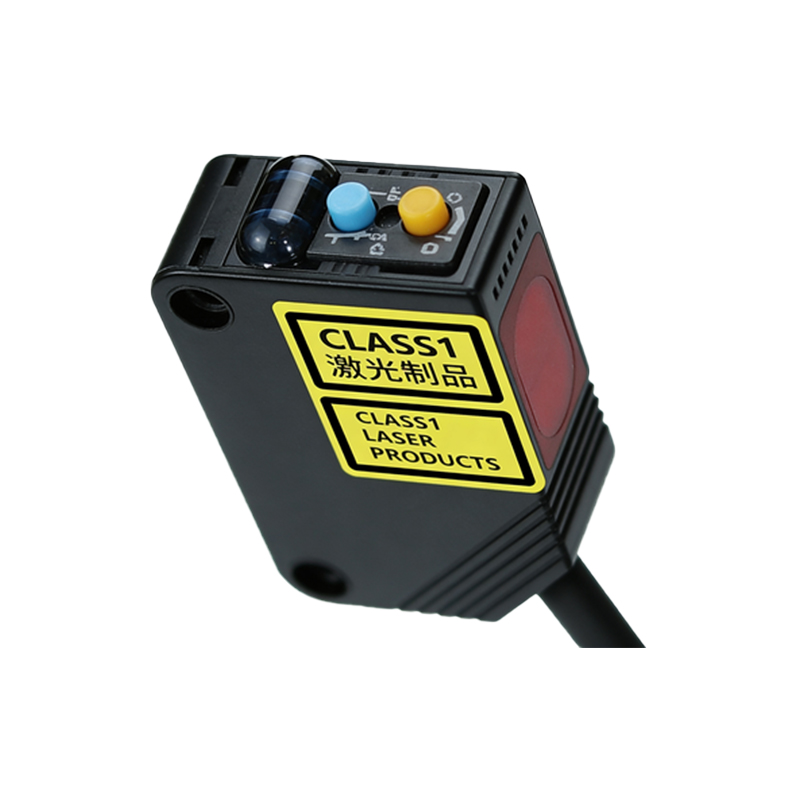
A thorough physical inspection is the first hands-on step. Begin by powering down the car wash system completely and locking out the power source to ensure safety. Visually examine the sensor lens for any accumulation of dirt, soap film, wax residue, or water droplets. Even a thin layer can scatter or block the light beam, causing intermittent failures. Clean the lens gently with a soft, lint-free cloth moistened with a suitable lens cleaner or isopropyl alcohol. Inspect the sensor housing for cracks, moisture ingress, or signs of impact damage from vehicles or moving equipment. Check all wiring connections at the sensor terminal block and follow the conduit back to the main control panel, looking for loose, corroded, or frayed wires. Ensure the sensor is mounted securely; vibration from nearby machinery can loosen mounting bolts, leading to misalignment. For through-beam and retro-reflective types, verify that the alignment between the emitter, receiver, and/or reflector is still true. A simple misalignment is one of the most common causes of perceived sensor failure.
Electrical Testing with a Multimeter
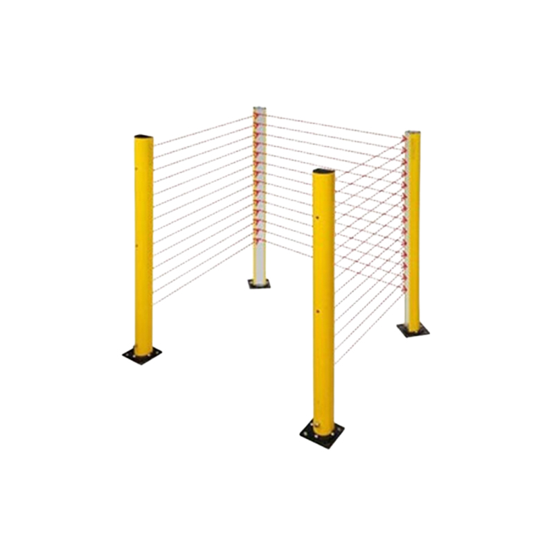
If the visual inspection reveals no issues, proceed with electrical testing using a digital multimeter (DMM). First, consult the sensor's datasheet to identify its wiring configuration (e.g., NPN/PNP, NO/NC) and voltage requirements (commonly 10-30V DC). With power safely restored, measure the voltage at the sensor's power supply terminals to confirm it is within the specified range. A low voltage could indicate a power supply issue rather than a sensor fault. Next, test the sensor's output. For a digital output sensor, set your DMM to measure DC voltage. Observe the output terminal voltage with the sensor's beam unobstructed (light state) and then obstructed (dark state). The voltage should switch distinctly between a high (e.g., close to supply voltage) and a low (e.g., near 0V) state, depending on its logic. A lack of change, a sluggish response, or an intermediate voltage suggests a faulty output circuit. For older or current-output sensors, you may need to measure the current loop (typically 4-20mA) in series. Always compare your readings against the manufacturer's specifications.
Functional Testing and Signal Monitoring
Functional testing under real or simulated operating conditions provides the most definitive diagnosis. Many modern sensors have a built-in signal strength indicator, often an LED that changes color or brightness relative to the received beam intensity. Use this feature during alignment or when a vehicle is present. For a more advanced analysis, an oscilloscope can be connected to the sensor's output signal line. A clean, fast-rising, and fast-falling square wave indicates a healthy switching sensor. A distorted, noisy, or slow-rise-time waveform suggests internal component degradation or electrical interference. You can also simulate operation by carefully interrupting the beam with an object while monitoring the system's PLC input status lights or software. If the PLC registers the change correctly but the machine still malfunctions, the issue likely lies elsewhere in the control logic or actuators. Conversely, if the PLC input does not change state, the sensor or its immediate wiring is at fault. Always perform tests with the system in a safe, manual, or maintenance mode to prevent unintended machine cycles.
Environmental Factors and Interference
Car wash environments are exceptionally harsh and can cause sensors to fail prematurely. Constant exposure to high-pressure water, steam, corrosive chemicals (soaps, waxes, acids), and wide temperature fluctuations stresses the sensor housing and seals. Even sensors rated IP67 or IP69K can fail if seals degrade. Direct or reflected sunlight can overwhelm the receiver of a diffuse or retro-reflective sensor, causing false triggers or loss of signal. Similarly, bright bay lighting or light from adjacent vehicle headlights can cause interference. Electrical noise from high-power motors, solenoids, or frequency drives can induce false signals on sensor wiring. Ensure sensor cables are properly shielded, routed away from power lines, and grounded according to code. Using sensors with modulated light (a specific pulsed frequency) greatly improves immunity to ambient light and optical interference. If a sensor repeatedly fails in a particular location, consider relocating it, adding a protective shield, or upgrading to a more robust model designed for severe duty.
Final Verification and Replacement Considerations
After cleaning, realigning, and testing, perform a final verification by running several complete car wash cycles with a test vehicle, if possible. Monitor for consistent, reliable detection throughout the entire sequence. If the problem persists and all other factors have been eliminated, sensor replacement is necessary. When selecting a replacement, match the electrical specifications (voltage, output type, current rating), mechanical form factor (size, mounting style, connector), and sensing characteristics (range, beam pattern) exactly. Consider upgrading to a newer model with enhanced environmental protection or diagnostic capabilities. During installation, meticulously follow the wiring diagram, ensure proper strain relief on cables, and realign the new sensor with precision. After