Understanding False Triggering in Photoelectric Sensors
False triggering in photoelectric sensors occurs when the sensor outputs an unintended signal due to environmental interference, incorrect installation, or component degradation. This phenomenon can disrupt automated processes, cause production errors, and lead to system downtime. Photoelectric sensors, which rely on light beams to detect objects, are susceptible to various external factors such as ambient light, dust, vibration, and electrical noise. Identifying the root cause is the first step toward implementing an effective solution. Engineers must analyze the sensor's operating environment, signal patterns, and historical performance data to pinpoint specific triggers. Common scenarios include intermittent detection failures, erratic output pulses, or continuous activation without physical object presence.
Environmental Factors and Mitigation Strategies
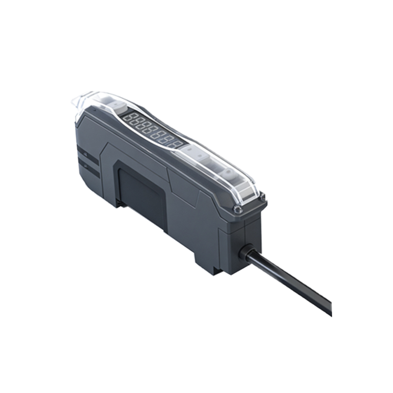
Ambient light interference, especially from sources like sunlight or high-intensity industrial lighting, can overwhelm a sensor's receiver, causing false triggers. To mitigate this, select sensors with modulated light technology, which uses pulsed infrared or laser beams to distinguish between ambient light and the sensor's own signal. Additionally, install physical shields or hoods around the sensor to block external light. Dust, dirt, or fog in the environment can scatter or block light beams, leading to unreliable detection. Regular cleaning of the lens and using sensors with higher ingress protection (IP) ratings, such as IP67 or IP69K, can prevent contamination-related issues. For environments with heavy particulate matter, consider sensors with air purge fittings or self-cleaning mechanisms.
Electrical Noise and Wiring Solutions
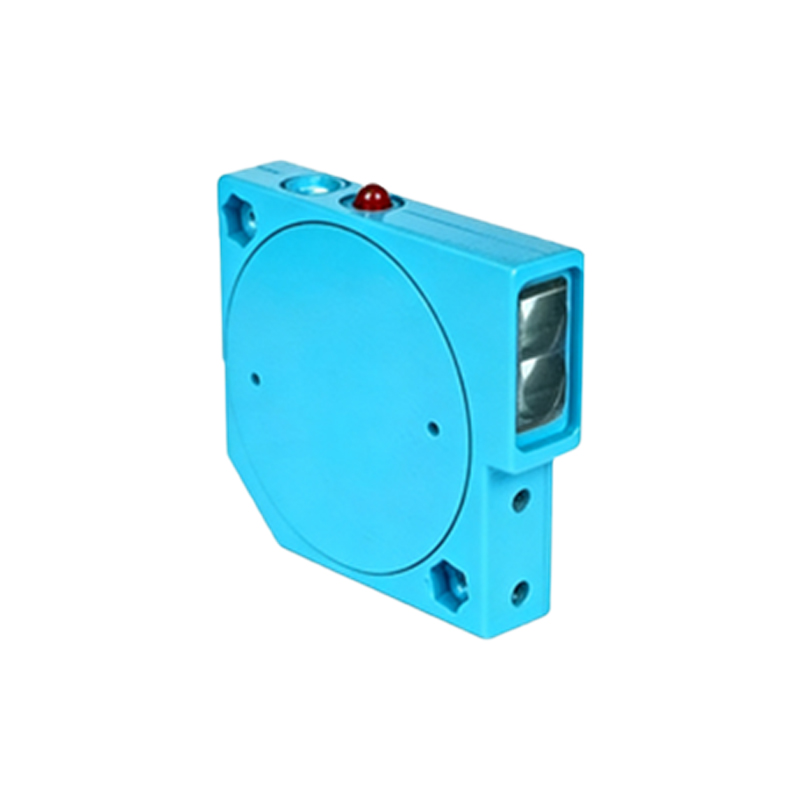
Electrical noise from motors, relays, or power lines can induce false signals in sensor circuits. This is particularly common in industrial settings with high electromagnetic interference (EMI). To address this, use shielded cables for sensor connections and ensure proper grounding of both the sensor and the control system. Twisted-pair wiring can also reduce noise pickup. Implement surge protectors or filters on power supply lines to suppress voltage spikes. For digital sensors, adjusting the response time or adding a delay function can help filter out transient noise. In severe cases, relocate the sensor away from high-noise equipment or use fiber-optic photoelectric sensors, which are immune to EMI due to their non-metallic components.
Installation and Alignment Best Practices
Incorrect installation is a leading cause of false triggering. Misalignment between the emitter and receiver in through-beam sensors, or improper mounting angles in reflective sensors, can result in weak or erratic signals. Always follow the manufacturer's guidelines for mounting distance, angle, and stability. Use alignment tools, such as laser pointers or built-in indicators, to ensure precise positioning. For retro-reflective sensors, avoid using highly reflective backgrounds that might bounce light back to the receiver unintentionally. In diffuse reflection sensors, adjust the sensitivity threshold to ignore background objects. Secure mounting brackets to prevent vibration-induced movement, which can cause intermittent alignment shifts.
Sensor Selection and Configuration Adjustments
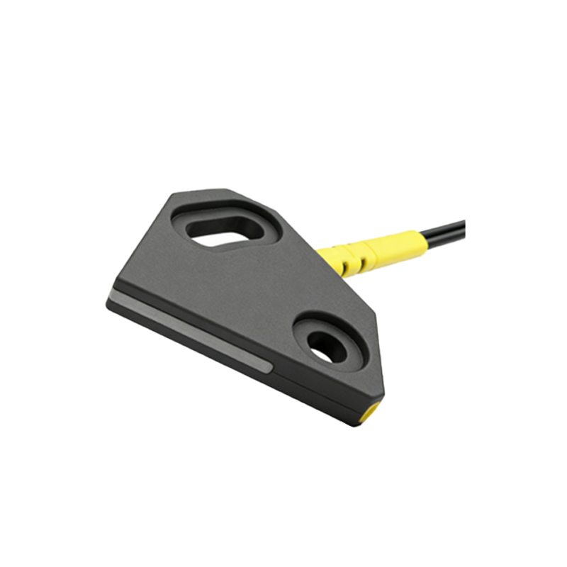
Choosing the right sensor type for the application is critical. Through-beam sensors offer the longest range and highest reliability but require separate emitter and receiver units. Retro-reflective sensors are easier to install but may be affected by reflective surfaces. Diffuse reflection sensors are compact but sensitive to object color and texture. Evaluate the detection range, response time, and environmental tolerance before selection. Once installed, configure the sensor settings appropriately. Adjust the sensitivity potentiometer to avoid detecting small particles or background interference. Enable teach-in functions for auto-calibration to adapt to changing conditions. For analog sensors, set appropriate threshold values to distinguish between valid and false signals.
Maintenance and Diagnostic Techniques
Regular maintenance can prevent false triggering caused by wear and tear. Schedule periodic inspections to check for lens cleanliness, cable integrity, and connector corrosion. Monitor the sensor's output using oscilloscopes or PLC diagnostics to identify irregular patterns. Many modern sensors feature diagnostic LEDs or communication protocols (e.g., IO-Link) that provide real-time status alerts for issues like signal strength degradation or temperature overload. Keep a log of false trigger incidents to identify recurring problems. Replace aging sensors proactively, as components like LEDs or phototransistors can degrade over time, reducing sensitivity and increasing error rates.
Advanced Troubleshooting and System Integration
When basic solutions fail, advanced troubleshooting may be necessary. Use signal analyzers to examine the sensor's output waveform for anomalies. Implement redundancy by installing multiple sensors in a voting logic configuration, where a trigger is only validated if two or more sensors agree. Integrate sensors with programmable logic controllers (PLCs) to add software-based filters, such as debounce timers or signal averaging algorithms. For wireless sensors, ensure stable communication channels and avoid frequency conflicts. Collaborate with sensor manufacturers for firmware updates or custom configurations tailored to specific industrial environments. Document all changes and solutions to build a knowledge base for future reference.