Understanding Photoelectric Sensors in Printers
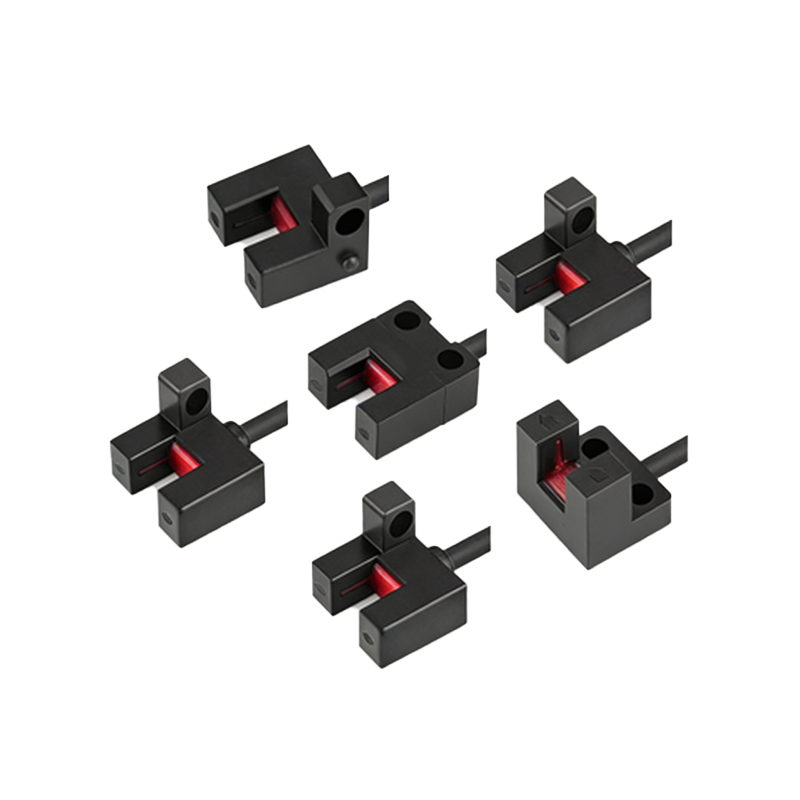
Photoelectric sensors are fundamental components in modern printers, responsible for critical functions such as paper detection, toner level monitoring, and print head positioning. These sensors operate by emitting a light beam—typically infrared or visible light—and detecting changes in the received light intensity caused by the presence or absence of an object. In printer mechanisms, they ensure precise paper feeding, prevent jams, and maintain print quality by providing real-time feedback to the control system. The reliability of these sensors directly impacts the printer's performance, making their correct installation and wiring, particularly polarity consideration, essential for optimal operation.
The Significance of Correct Polarity
Polarity refers to the positive and negative terminals of a sensor's power supply. In DC-powered photoelectric sensors, reversing the polarity can lead to immediate failure or permanent damage. The sensor's internal circuitry, including the light-emitting diode (LED) and phototransistor, is designed to function with a specific voltage direction. Incorrect polarity may cause the LED to not illuminate, rendering the sensor non-responsive, or worse, result in overheating and component burnout. In printers, this can manifest as persistent error messages, paper feed failures, or inaccurate toner level readings, disrupting workflow and increasing maintenance costs.
Identifying Positive and Negative Terminals
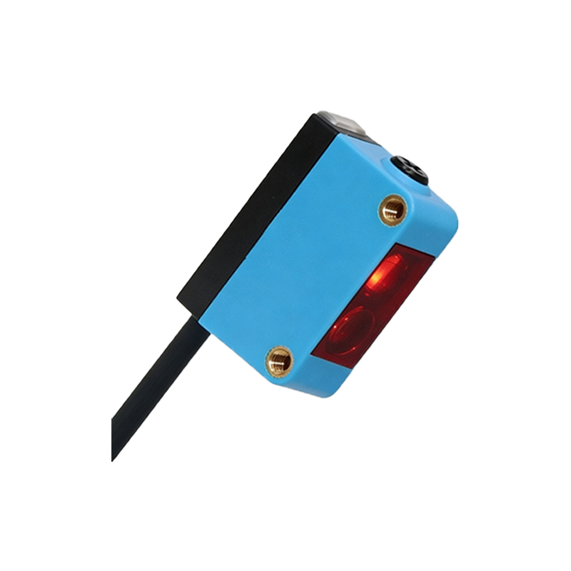
Most printer photoelectric sensors feature clear markings to indicate polarity. Common identifiers include symbols such as "+" for positive and "–" for negative, color-coded wires (e.g., red for positive, black for negative), or labels like Vcc (power supply) and GND (ground). Engineers should consult the printer's service manual or sensor datasheet for precise specifications. For instance, in compact sensors used in paper trays, the positive terminal often connects to the printer's low-voltage DC supply (e.g., 5V or 12V), while the negative terminal links to the common ground. Using a multimeter in continuity mode can verify connections if markings are ambiguous.
Wiring Practices and Safety Considerations
Proper wiring is crucial to avoid polarity-related issues. Always power off the printer and disconnect it from the electrical outlet before handling sensors. Use insulated tools and follow electrostatic discharge (ESD) precautions to protect sensitive components. When replacing a sensor, double-check the wire routing against the original setup or schematic diagrams. For soldering connections, ensure correct alignment of terminals and avoid short circuits. In industrial-grade printers, where sensors may interface with programmable logic controllers (PLCs), adhere to wiring standards such as IEC 61131-2 to maintain system integrity and safety.
Troubleshooting Polarity Problems
If a printer exhibits sensor-related malfunctions, polarity should be a primary checkpoint. Symptoms of reversed polarity include no response from the sensor, erratic behavior, or burnt components. Begin by visually inspecting the sensor and its wiring for damage or discoloration. Use a multimeter to measure voltage at the sensor terminals; a negative reading indicates reversed polarity. If identified, correct the wiring immediately. Additionally, test the sensor independently by applying correct polarity from a bench power supply to confirm functionality. Document any findings to aid future maintenance and prevent recurrence.
Impact on Printer Performance and Longevity
Correct polarity ensures that photoelectric sensors operate within their designed parameters, contributing to consistent printer performance. Sensors with proper polarity deliver accurate signals, enabling precise timing for paper advancement and reducing wear on mechanical parts like rollers and gears. Over time, this minimizes downtime and extends the printer's lifespan. In high-volume environments, such as offices or print shops, attention to polarity during installation and repairs can significantly lower total cost of ownership by avoiding frequent replacements and service calls.
Best Practices for Engineers and Technicians
To master polarity management, engineers should develop a systematic approach. Always reference technical documentation before installation. Label wires and terminals during disassembly to simplify reassembly. Invest in quality tools, such as polarized test leads and diagnostic software, for accurate assessments. Participate in training sessions on printer electronics to stay updated on sensor technologies. By prioritizing polarity accuracy, professionals can enhance reliability, ensure user satisfaction, and uphold safety standards in electrical systems. Remember, in photoelectric sensors, attention to detail with positive and negative connections is not just a technicality—it's a cornerstone of efficient printer operation.