Introduction to Inductive Proximity Sensor Frequency
The operational frequency of an inductive proximity sensor is a critical parameter that directly influences its performance, responsiveness, and suitability for specific applications. Fundamentally, this frequency refers to the rate at which the sensor can detect and signal the presence or absence of a metallic target. It is often specified as the switching frequency or response frequency, measured in Hertz (Hz). A higher frequency indicates a faster sensor capable of detecting rapidly moving or small targets, while a lower frequency may be sufficient for slower, more static applications. Understanding this characteristic is essential for engineers to integrate these sensors effectively into automation systems, machinery, and production lines where timing and precision are paramount.
The Core Principle: How Frequency is Generated
At the heart of an inductive proximity sensor lies an LC oscillator circuit, where 'L' stands for the inductance of the coil and 'C' for capacitance. This circuit generates a high-frequency electromagnetic field at the sensing face. When a metallic target enters this field, eddy currents are induced on the target's surface. These eddy currents draw energy from the oscillator, causing a change in its amplitude or frequency. The sensor's internal circuitry detects this change and triggers the output switch. The base frequency of the electromagnetic field, typically ranging from tens of kHz to several MHz, is a design constant. However, the measurable output parameter for users is the maximum switching frequency—how many times per second the sensor's output can reliably change state (from ON to OFF and back) in response to a target.
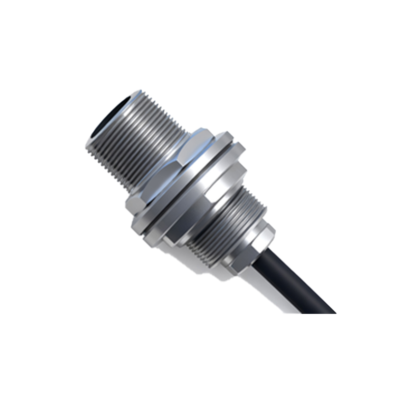
Key Factors Influencing Switching Frequency
Several factors determine the maximum achievable switching frequency of a sensor. First is the sensor's physical size and design; smaller sensors with compact coils often have higher natural resonant frequencies and can respond faster. Second, the target material plays a role. Ferrous metals (like iron and steel) typically cause a stronger damping effect than non-ferrous metals (like aluminum or copper), which can influence the sensor's response time and thus its effective switching frequency. Third, the sensing distance is crucial. Operating at the nominal sensing distance (Sn) provides optimal performance. If the target operates at a reduced distance, the switching frequency can often be increased. Finally, the sensor's output circuitry (PNP/NPN, analog, or IO-Link) and any internal signal processing or filtering will impose limits on how quickly the output can toggle.
Practical Implications and Application Selection
Selecting a sensor with an appropriate switching frequency is vital for application success. For high-speed applications such as counting small parts on a fast conveyor, detecting teeth on a rotating gear, or monitoring the position of a high-speed actuator, sensors with switching frequencies of 1 kHz to 5 kHz or even higher are necessary. Using a sensor with a 100 Hz frequency in such a scenario would result in missed counts and system errors. Conversely, for applications like end-position detection of a slowly moving cylinder or door open/close monitoring, a standard sensor with a lower frequency (e.g., 100 Hz) is perfectly adequate and often more cost-effective. Exceeding the required speed specification unnecessarily can sometimes lead to increased sensitivity to electrical noise or higher power consumption.
Relationship with Response Time and Duty Cycle
Switching frequency is intrinsically linked to the sensor's response time. The response time is the duration required for the output to change state after the target enters or leaves the sensing field. It is usually specified as ton (turn-on delay) and toff (turn-off delay). The maximum switching frequency (fmax) can be approximated by the formula: fmax ≈ 1 / (ton + toff). For instance, a sensor with a combined response time of 1 ms can theoretically achieve a switching frequency up to 1 kHz. Additionally, the duty cycle—the ratio of pulse width to pulse period in a periodic signal—must be considered. For reliable operation at high frequencies, a 1:1 duty cycle (equal ON and OFF times) is typically recommended to ensure the sensor's electronics have sufficient time to reset.
Advanced Considerations and Modern Trends
Modern inductive sensors offer features that enhance frequency-related performance. Sensors with teach-in functionality or IO-Link communication allow for dynamic adjustment of parameters like switching hysteresis, which can optimize performance for specific target speeds and materials, indirectly influencing effective frequency stability. Furthermore, high-frequency immune (HFI) or noise-resistant designs are critical in environments with strong electromagnetic interference from variable frequency drives (VFDs) or welding equipment, as noise can cause false triggering that mimics a high-frequency signal. The trend towards miniaturization and integration with smart factory concepts (Industry 4.0) continues to push the development of sensors that are not only faster but also