Introduction to Photoelectric Sensors in UG Environments
Photoelectric sensors are indispensable components in modern industrial automation, particularly within Siemens NX (UG) design and simulation environments. These sensors operate by emitting a light beam—typically infrared, visible red, or laser—to detect the presence, absence, or distance of an object. In UG software, engineers and designers utilize detailed 2D and 3D models, assembly diagrams, and schematic representations to integrate these sensors into larger mechanical and electrical systems. A comprehensive UG image collection serves as a critical visual reference library, showcasing sensor form factors, mounting configurations, wiring interfaces, and operational principles. This visual database accelerates the design process, ensures compatibility, and facilitates precise simulation of sensor behavior in virtual prototypes before physical implementation.
Core Components and Types Illustrated in UG Models
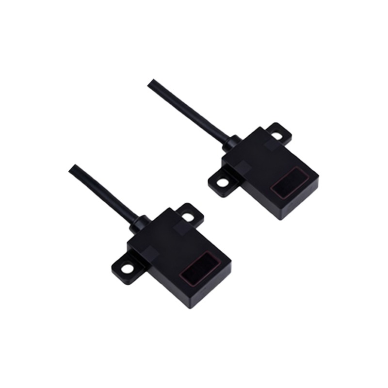
A thorough UG image gallery categorizes photoelectric sensors by their fundamental operating modes: through-beam, retro-reflective, and diffuse reflective. Through-beam sensor models depict separate emitter and receiver units, highlighting alignment critical for long-range detection. Retro-reflective models show a single housing combining emitter and receiver, with a reflector component, ideal for moderate distances. Diffuse reflective sensor illustrations focus on the integrated design where light reflects directly off the target object. Advanced UG renderings also detail specialized variants like background suppression sensors, color mark sensors, and fiber optic units. Cross-sectional views within UG files reveal internal optics, lens types, LED light sources, and electronic circuitry, providing deep insight into mechanical and optical design constraints.
Mounting and Integration Schematics in UG Assemblies
Effective integration of photoelectric sensors into machinery requires precise mechanical mounting and electrical interfacing. UG assembly drawings and exploded views demonstrate standard mounting brackets, adjustable holders, and protective housings for harsh environments. These images illustrate key dimensional tolerances, thread specifications (e.g., M8, M12, M18), and alignment features. Furthermore, UG schematic diagrams detail electrical connections, showing pin assignments for power supply (typically 10-30V DC), output signals (PNP/NPN, NO/NC), and communication buses (IO-Link). Wiring harness layouts and cable gland models are often included, emphasizing best practices for noise immunity, strain relief, and compliance with IP67 or IP69K ingress protection ratings as modeled in UG's simulation modules.
Application-Specific UG Imagery for Industry Solutions
Contextual application images within UG environments bridge the gap between generic sensor models and real-world use cases. These visuals depict sensors in simulated action on conveyor belts for object counting, on robotic arms for pick-and-place position verification, inside packaging machines for label detection, and along assembly lines for part orientation checks. UG animations can showcase the sensing beam's path, the detection zone (spot size or beam shape), and the response to different target materials (transparent, opaque, glossy). Such application-specific galleries help engineers select the optimal sensor model, define installation parameters, and troubleshoot potential interference from ambient light or environmental contaminants during the virtual design phase.
Leveraging UG Images for Simulation and Validation
Beyond static imagery, UG models enable dynamic simulation of photoelectric sensor systems. Motion studies can animate the interaction between a moving target and the sensor's detection logic, validating timing sequences for high-speed applications. Photorealistic renderings with accurate material properties and lighting conditions assess how sensor performance might be affected by colored objects or surface finishes. Thermal and stress analysis modules can evaluate the sensor housing's durability. These simulation-ready UG images and models form a digital twin, allowing for comprehensive performance prediction, lifecycle testing, and optimization of the entire sensing system without physical prototyping, thereby reducing development time and cost.
Building and Utilizing a Professional UG Image Library
Creating a valuable "UG image大全" (comprehensive collection) involves systematic curation. Sources include manufacturer-provided CAD libraries (often in STEP or native UG .prt format), in-house generated models, and detailed screenshots from UG simulation sessions. Each image should be tagged with metadata: sensor model number, detection range, light source type, output configuration, and relevant industry standards. This library becomes a central knowledge repository for design teams, supporting tasks from initial concept layouts to creating technical documentation and training materials. Regular updates with new sensor families and UG software features ensure the collection remains an authoritative, time-saving resource for engineers designing the next generation of automated systems.