Introduction to Photoelectric Sensor Wiring
A photoelectric sensor is a cornerstone of modern industrial automation, detecting the presence, absence, or distance of an object using a light transmitter and receiver. While the sensing principle is straightforward, correct electrical wiring is paramount for reliable operation and system safety. This guide, inspired by practical wiring video tutorials, will walk you through the essential steps and considerations for connecting photoelectric sensors in typical control circuits. Understanding these connections prevents downtime, protects equipment, and ensures optimal sensor performance in demanding environments.
Understanding Sensor Specifications and Wiring Diagrams
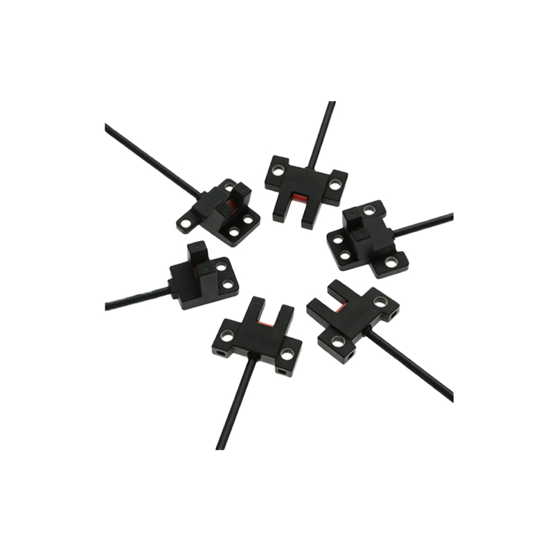
Before touching any wires, the first critical step is to consult the sensor's datasheet. Identify the sensor type: diffuse, retro-reflective, or through-beam. Crucially, note the electrical specifications: operating voltage (commonly 10-30V DC or 90-250V AC), output type (PNP-sourcing or NPN-sinking for DC; relay or solid-state for AC), and output function (normally open NO or normally closed NC). The wiring diagram, typically found on the sensor's housing or manual, is your blueprint. It clearly shows terminals for power supply (V+ or L1, V- or L2), the output signal (often labeled OUT or NO/NC), and sometimes a separate wire for diagnostics or timing functions. Misinterpreting this diagram is a primary cause of installation failure.
Essential Tools and Safety Precautions
Gather the necessary tools: appropriate screwdrivers, wire strippers, crimping tools, ferrules for stranded wire, and a multimeter for verification. Safety is non-negotiable. Always lock out and tag out (LOTO) the main power supply before beginning any wiring work. Ensure the control cabinet is de-energized. Verify that the sensor's voltage rating matches your power source. Using personal protective equipment (PPE) like safety glasses and insulated gloves is a standard best practice. A systematic and safe approach prevents electrical hazards and equipment damage.
Step-by-Step DC Sensor Wiring (PNP/NPN)
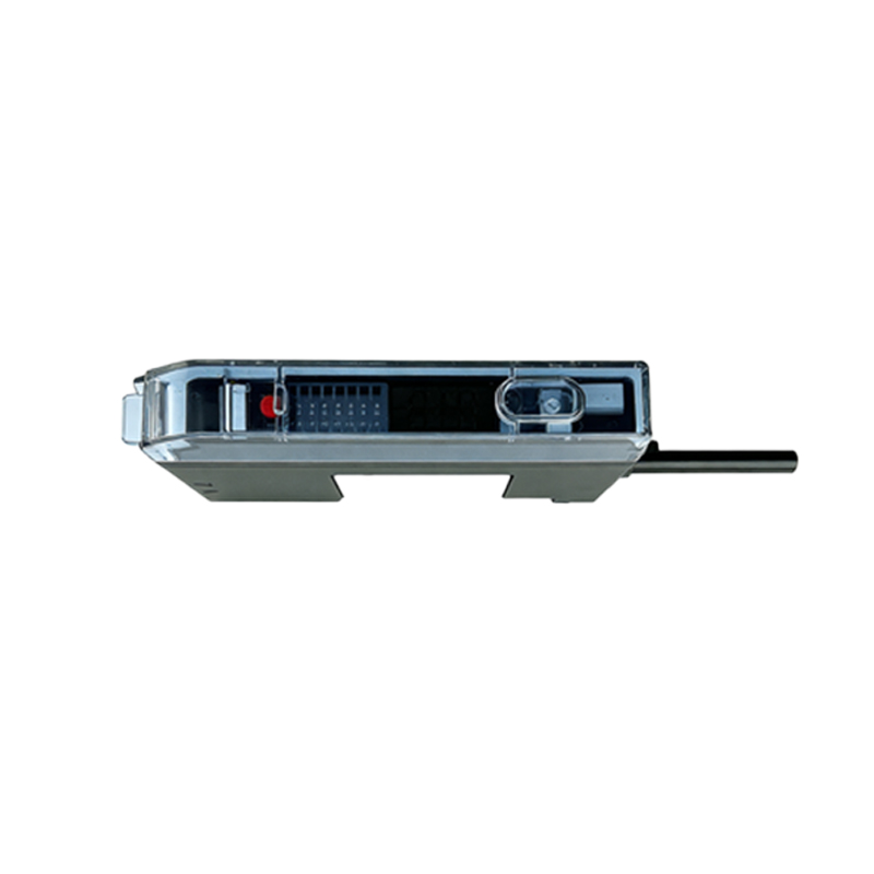
For a common 3-wire DC sensor (e.g., 24V DC), the process is systematic. First, connect the brown wire (universally V+ or positive) to the positive terminal of your 24V DC power supply. Connect the blue wire (universally V- or 0V) to the negative terminal or common ground. The third wire (often black, white, or gray) is the switched output. For a PNP (sourcing) sensor, this output wire provides positive voltage when active. Connect it to the input terminal of your controller (PLC, relay). The controller's input common is then connected to the power supply negative. For an NPN (sinking) sensor, the output wire sinks current to negative when active. Connect it to the controller input, and the controller's input common is connected to the power supply positive. Always secure connections tightly and use cable glands for strain relief.
Step-by-Step AC Sensor Wiring
Wiring an AC-powered sensor (e.g., 120V AC) involves higher voltage, demanding extra caution. Typically, these sensors have two power wires (often brown and blue) and output wires. Connect the brown wire to the hot (line) AC terminal and the blue wire to the neutral. The output is usually a relay contact or solid-state switch. Connect one output terminal to your load (e.g., a coil of a larger contactor), and connect the other side of that load to the neutral or hot wire, completing the circuit as per the diagram. Ensure all connections are insulated, and the sensor body is properly grounded if a ground terminal is present, to prevent shock and electrical noise.
Connecting to a PLC Input Module
Integrating the sensor with a Programmable Logic Controller (PLC) is a frequent application. The key is matching the sensor output type to the PLC input type. A PNP sensor pairs with a sinking PLC input card (where the card's common is connected to negative). An NPN sensor pairs with a sourcing PLC input card (where the card's common is connected to positive). Mismatching these can lead to the sensor not being detected or, worse, damaging the input circuit. After wiring, use the PLC programming software to monitor the input status to confirm the sensor triggers correctly when an object is detected.
Testing and Troubleshooting Common Issues
After wiring, apply power cautiously. Observe the sensor's indicator LED. A steady power LED indicates good voltage supply. A blinking or absent LED suggests incorrect power wiring. Test the sensing function by introducing a target object. The output LED should activate. Use a multimeter to measure voltage between the output wire and common: it should switch from 0V to ~24V (for PNP) or 24V to 0V (for NPN) when activated. Common issues include no response (check power and wiring polarity), inconsistent detection (check alignment, sensing range, and environmental factors like ambient light or dirt), or constant output (possible wiring short or sensor failure). Always refer back to the diagnostic indicators on the sensor itself.
Best Practices for Installation and Maintenance
Proper installation extends sensor life. Use shielded cables in electrically noisy environments, connecting the shield to ground at one end only. Ensure wires are not run parallel to high-power cables to avoid interference. Provide adequate mechanical protection for cables. Periodically clean the sensor lens to maintain optical performance. Document your wiring schematics for future maintenance. Following these best practices, as visually demonstrated in quality wiring videos, ensures a robust, reliable, and safe photoelectric sensing system that forms a dependable part of your automation infrastructure.