Understanding Proximity Sensor Fundamentals
Proximity sensors are non-contact devices designed to detect the presence or absence of an object within a specific sensing range. Unlike mechanical limit switches, they operate without physical contact, making them ideal for applications requiring high reliability, fast response, and minimal wear. The core principle involves generating an electromagnetic field, light beam, or ultrasonic signal. When a target object enters this field, it causes a detectable change in the sensor's state, which is then converted into an electrical output signal. Recognizing a proximity sensor typically involves identifying its housing, which is often cylindrical or rectangular, made of metal or polymer, and features an LED indicator light and electrical connection points. The sensing face is a key visual cue, distinct from the rest of the housing.
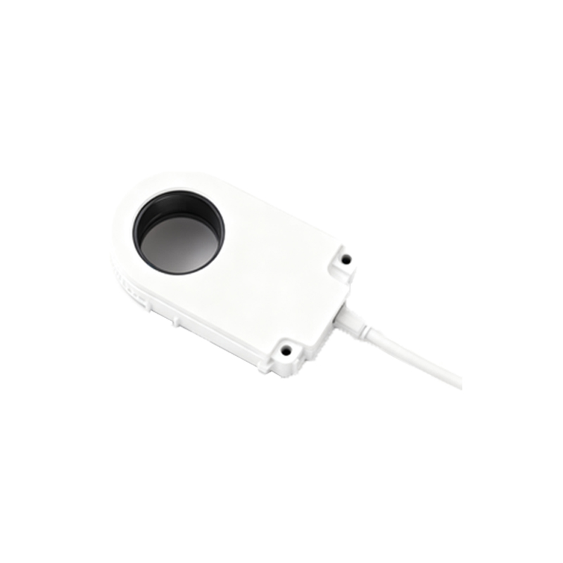
Visual Identification and Key Markings
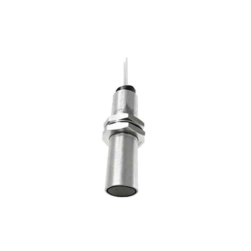
Identifying a proximity sensor by sight requires checking several physical and labeled characteristics. First, examine the body for manufacturer logos and a model number. This alphanumeric code is crucial for determining the sensor's type, sensing range, output configuration, and electrical specifications. Second, look for standardized symbols and abbreviations. Inductive sensors, which detect metals, are often marked with a coil symbol or "IN." Capacitive sensors, detecting both metallic and non-metallic materials, may show a capacitor symbol or "CA." Ultrasonic sensors might display a sound wave icon. Photoelectric sensors, using light beams, often have a lens and emitter/receiver indicators. The housing color can also be a hint; many inductive sensors have nickel-plated brass or stainless steel barrels.
Interpreting Electrical Specifications
Once physically identified, understanding how to use it depends on correctly interpreting its electrical ratings. These are always printed on the label. Critical parameters include the operating voltage (e.g., 10-30V DC or 90-250V AC), output type (PNP/NPN for DC, or relay/SSR for AC), and current rating. The output type is paramount for wiring. A PNP sensor switches the positive voltage to the load, while an NPN switches the negative side. Miswiring can damage the sensor or the controller. The sensing distance, denoted as "Sn," is also specified. It's vital to note that the effective sensing range can be influenced by the target material's size, shape, and composition, especially for inductive and capacitive types.
Wiring and Installation Procedures
Proper installation is key to reliable operation. For a standard 3-wire DC sensor, the wires are typically brown (positive), blue (negative/common), and black (output signal). The brown wire connects to the positive supply, blue to the negative, and the black wire connects to the input of a PLC, relay, or other control device. Ensure the sensor is securely mounted, avoiding any metal surfaces within the lateral sensing area that could cause false triggering. Maintain the recommended mounting distance between multiple sensors to prevent mutual interference. For cylindrical sensors, flush-mounted models can be installed level with a metal bracket, while non-flush types require a clear space around the sensing face.
Functional Testing and Diagnostics
After installation, functional testing confirms correct operation. Power the sensor and observe its indicator LED. Most sensors have a stable or blinking LED when powered and no target is present. When a valid target is brought within the sensing range, the LED should change state (e.g., turn on or off), indicating detection. Use a multimeter to verify the output voltage switch. For troubleshooting, common issues include no output signal (check power, wiring, and target material), shortened sensing range (check for sensor damage or dirty sensing face), and erratic operation (check for electrical noise or environmental interference like cutting fluids). Always refer to the datasheet for specific diagnostic patterns indicated by the LED.
Application-Specific Selection Criteria
Choosing the right sensor for an application goes beyond mere identification. Consider the target material: inductive for metals, capacitive for plastics/liquids, photoelectric for precise position, and ultrasonic for distance measurement or transparent objects. Evaluate the required sensing distance and whether a analog output (for distance proportionality) or discrete on/off signal is needed. Environmental factors are critical; sensors in washdown areas need high IP ratings (e.g., IP67, IP69K), while those in high-temperature zones must have appropriate thermal ratings. For high-speed counting on a production line, select a sensor with a fast response frequency. Understanding these criteria ensures the identified sensor is applied effectively and reliably in its intended role.