Introduction to Photoelectric Sensors and Timer Relays
In industrial control systems, photoelectric sensors and timer relays are fundamental components that work in tandem to create precise, automated sequences. A photoelectric sensor detects the presence, absence, or distance of an object using a light transmitter and receiver. Timer relays, on the other hand, are control devices that introduce a time delay in the activation or deactivation of a circuit. When combined, they enable sophisticated functions such as delayed start-up, timed operation cycles, or object counting with controlled intervals. This integration is crucial for applications ranging from conveyor belt management to packaging machinery and automated assembly lines. Understanding the operational principles of both devices is the first step toward a successful and reliable interconnection.
Understanding the Electrical Specifications
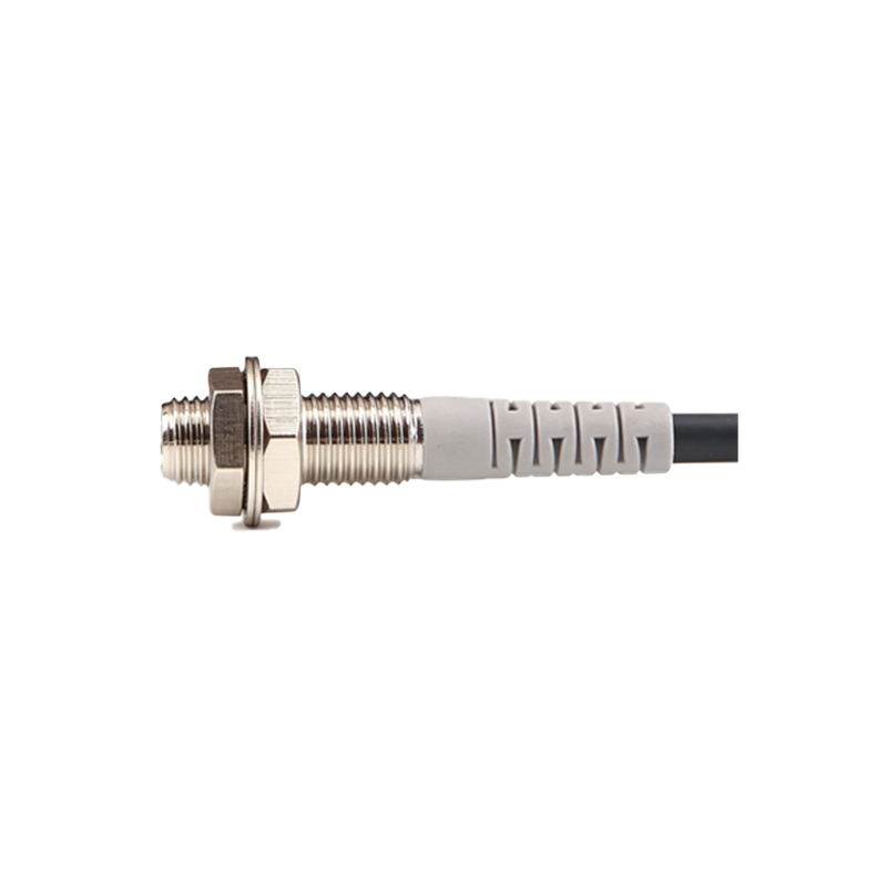
Before attempting any wiring, a thorough review of the electrical specifications for both the photoelectric sensor and the timer relay is paramount. Photoelectric sensors are typically available in two main output types: NPN (sinking) and PNP (sourcing), which correspond to the type of transistor output and determine the current flow direction. Timer relays have specific coil voltage requirements (e.g., 12VDC, 24VDC/AC, 120VAC) and contact configurations (e.g., SPDT, DPDT). The sensor's output current rating must be compatible with the timer relay's coil input requirements. Mismatched voltages or current capacities can lead to device failure, unreliable operation, or permanent damage. Always consult the manufacturer's datasheets to confirm compatibility.
Wiring Configuration for a Standard Setup
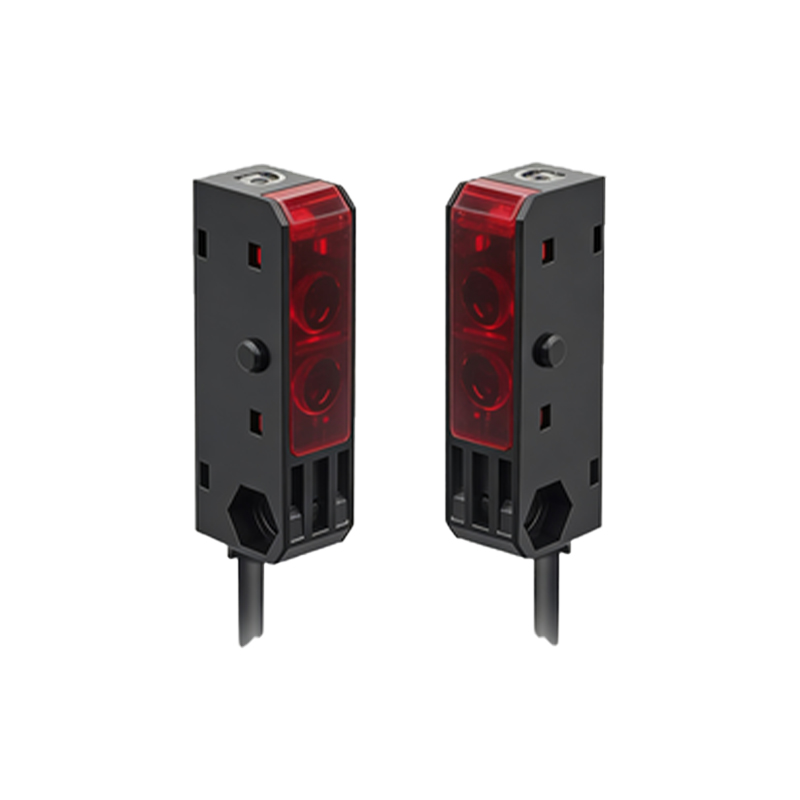
A common configuration involves using the sensor to trigger the timer relay's coil. For a DC system using a PNP sensor, connect the positive power supply lead to the sensor's positive terminal and the timer relay's coil positive terminal. Connect the negative power supply lead to the sensor's negative terminal and the common terminal of the relay coil. The sensor's output wire (often brown or black) is then connected to the remaining terminal of the timer relay's coil. When the sensor detects an object, it activates its output, completing the circuit to energize the relay coil. This action starts the timer's internal delay cycle. The relay's timed contacts, which are separate from the coil terminals, can then be wired to control a load like a motor, solenoid, or indicator lamp after the preset delay.
Configuring the Timer Relay Operation Mode
Timer relays offer various modes of operation, and selecting the correct one is critical for the intended application. The most frequently used modes for sensor integration are On-Delay (Delay on Make) and Off-Delay (Delay on Break). In an On-Delay configuration, when the sensor energizes the coil, the relay's output contacts change state only after the set time delay has elapsed. This is ideal for starting a process a specific time after an object is detected. In an Off-Delay configuration, when the sensor signal stops (the coil de-energizes), the relay's contacts remain in their energized state for the preset delay before returning to their normal state. This is useful for keeping a machine running for a set time after an object passes. The delay time is typically set using dials, dip switches, or digital interfaces on the relay.
Practical Application Example: Conveyor Zone Control
Consider a conveyor system where a box must trigger a stamping mechanism five seconds after it is detected at a specific point. A retro-reflective photoelectric sensor is positioned to detect boxes. It is wired to the coil of an On-Delay timer relay set for a 5-second delay. The normally open contact of the timer relay is wired in series with the control circuit for the pneumatic stamping cylinder. When a box breaks the sensor's beam, the sensor output activates, energizing the timer relay's coil. After precisely 5 seconds, the timer relay's contact closes, activating the stamping cylinder to mark the box. This ensures the stamp occurs at the correct position on the conveyor, demonstrating a simple yet effective automation sequence.
Safety Considerations and Best Practices
Safety is non-negotiable in industrial electrical work. Always disconnect and lock out all power sources before beginning installation or wiring. Use properly rated wires and secure connections to prevent arcing or overheating. Implement protective devices such as fuses or circuit breakers on the power supply lines. For the control circuit, consider adding a master emergency stop switch that cuts power to the entire system. It is also a best practice to clearly label all wires and components according to the wiring diagram. After installation, perform a thorough functional test with the system in a safe, controlled manner before integrating it into full production. Regular maintenance checks should include verifying sensor alignment, cleaning optical components, and testing the accuracy of the timer delay.
Troubleshooting Common Connection Issues
Even with careful planning, issues may arise. If the timer relay does not activate, first verify power is present at both the sensor and relay. Check for correct wiring polarity, especially in DC systems. Confirm the sensor's output type (NPN/PNP) matches the expected input for the relay coil. Use a multimeter to test if the sensor is providing the correct output voltage when an object is detected. If the relay activates but the timing is inaccurate, verify the delay setting and mode on the timer relay. Intermittent operation can often be traced to loose wire connections, electrical noise interference, or a misaligned/dirty photoelectric sensor. Isolating each component and testing them independently is the most effective troubleshooting methodology.