Understanding the Components
A 12V photoelectric sensor is a versatile device used for detecting the presence, absence, or distance of an object using a light transmitter and receiver. Commonly employed in industrial automation, security systems, and safety applications, it operates on a 12V DC power supply, making it compatible with a wide range of standard alarm systems and control panels. The alarm, typically a siren, buzzer, or strobe light, serves as the output device to provide an audible or visual alert when the sensor is triggered. Successful integration hinges on a clear understanding of the sensor's specifications—such as its output type (e.g., NPN or PNP transistor, relay contact) and wiring requirements—and the alarm's input characteristics.
Pre-Connection Planning and Safety
Before initiating any wiring, thorough planning is essential to ensure a safe and functional setup. First, always disconnect all power sources to prevent electrical shock or damage to components. Review the datasheets for both the photoelectric sensor and the alarm device. Identify the power terminals (usually labeled V+ and V- or COM), the output signal terminal from the sensor, and the trigger input terminal on the alarm. For a 12V system, you will need a suitable 12V DC power supply with adequate current rating to power both devices. Gather necessary tools: wire strippers, crimping tools, screwdrivers, and appropriate gauge electrical wires. It is also prudent to have a multimeter on hand for voltage and continuity checks. Plan the physical layout, considering the sensor's sensing range and the desired location for the alarm indicator.
Wiring the Power Supply
The foundational step is establishing a common 12V DC power rail. Connect the positive terminal (V+) of your 12V DC power supply to the positive power input terminal on both the photoelectric sensor and the alarm unit. Similarly, connect the negative terminal (V- or COM) of the power supply to the negative/common terminals of both devices. This creates a shared ground reference, which is critical for the signal interface to work correctly. Use twisted-pair or shielded cable for longer runs to minimize electrical noise interference, which is crucial for the stable operation of the photoelectric sensor. Secure all connections firmly to avoid loose wires that could lead to intermittent faults. After completing the power wiring, a preliminary check with a multimeter can confirm that 12V is correctly present at the terminals of each device before proceeding.
Interfacing the Sensor Output with the Alarm Input
This is the core of the connection, where the sensor's detection signal activates the alarm. The method depends heavily on the sensor's output type. For a sensor with a relay contact output, connect one side of the relay's switch terminal to the 12V+ line (or a separate positive source, as per alarm specs). Connect the other side of the relay terminal to the trigger input terminal of the alarm. The alarm's other trigger terminal is connected to the common (V-). When the sensor detects an object, the relay closes, completing the circuit and activating the alarm. For a sensor with an NPN transistor output (sinking), the output terminal acts as a switch to ground. Connect the alarm's trigger input to the 12V+ supply. Then, connect the other alarm trigger terminal to the sensor's output wire. When activated, the NPN transistor sinks current to ground, completing the path and triggering the alarm. For a PNP transistor output (sourcing), the logic is reversed; the output provides a positive voltage. Always verify the alarm's input compatibility—some are designed for dry contacts (relay), while others accept voltage signals directly.
Configuration and Testing
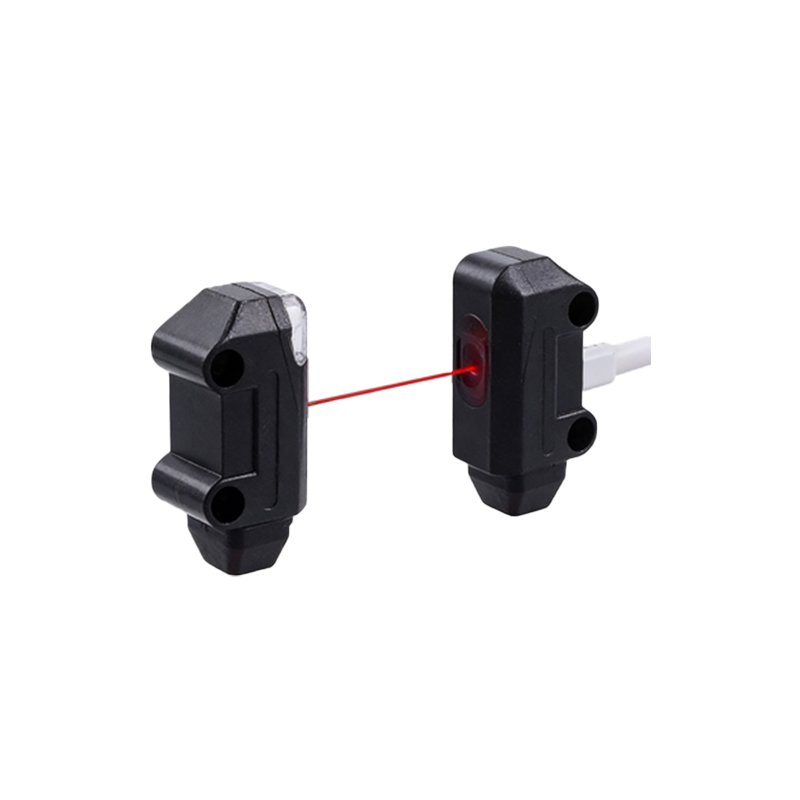
Once the physical wiring is complete, apply power to the system. Most 12V photoelectric sensors have indicator LEDs for power and output status. Configure the sensor's sensing mode (e.g., light-on or dark-on) using its built-in switches or teach-in function, depending on the desired logic—whether the alarm should trigger upon beam interruption or upon beam reception. Adjust the sensitivity and response time if necessary. To test, simulate the detection condition. For a through-beam sensor, break the light path between the separate transmitter and receiver. For a reflective sensor, place an object within its sensing range. Observe the sensor's output LED and listen or watch for the alarm activation. Use the multimeter to probe the voltage at the alarm's trigger terminals during activation to confirm the signal is being received correctly. Conduct several test cycles to ensure consistent and reliable operation.
Troubleshooting Common Issues
If the system does not function as expected, a systematic approach is key. First, re-check all wiring connections against your plan and the manufacturers' diagrams. Verify power is present at both devices. If the alarm does not sound, bypass the sensor by temporarily connecting the alarm trigger input directly to the activating signal (ground for NPN, 12V+ for PNP or relay). If the alarm activates, the issue lies with the sensor or its wiring. Check the sensor's alignment and lens cleanliness; misalignment is a frequent cause of failure. Ensure the detected object is within the specified sensing distance and is suitable for the sensor's type (e.g., reflective sensors may struggle with dark, non-reflective objects). Electrical noise can cause false triggering; ensure proper grounding and use of shielded cables. Consult the device manuals for specific error indicators or diagnostic procedures.
Applications and Best Practices
A successfully connected 12V photoelectric sensor and alarm system finds use in numerous applications. In security, it can protect perimeters by detecting intrusions. In industrial settings, it can signal when a production bin is full or when a safety guard is opened. For reliable long-term operation, adhere to best practices: protect the wiring in conduits in harsh environments, use drip loops outdoors to prevent water ingress into connections, and label all wires clearly for future maintenance. Periodically clean the sensor's lens and realign if necessary. Consider adding a manual reset switch or integrating the system with a programmable logic controller (PLC) for more complex logic and system integration. This simple yet robust interconnection forms a fundamental building block for automated monitoring and alerting across various sectors.