Understanding Proximity Sensor Fundamentals
Before diving into the wiring process, it's crucial to understand the basic types of proximity sensors commonly used in industrial automation. The two primary categories are inductive and capacitive sensors. Inductive sensors detect metallic objects, while capacitive sensors can detect both metallic and non-metallic materials. Furthermore, sensors are classified by their output configuration: NPN (sinking) and PNP (sourcing). An NPN sensor switches the negative side of the load to the common negative, whereas a PNP sensor switches the positive side to the common positive. Incorrect identification of the sensor type is the leading cause of wiring failures and potential damage to the sensor or the programmable logic controller (PLC). Always refer to the manufacturer's datasheet, which provides the electrical schematic, voltage ratings, and connection diagrams specific to your model.
Essential Tools and Safety Precautions
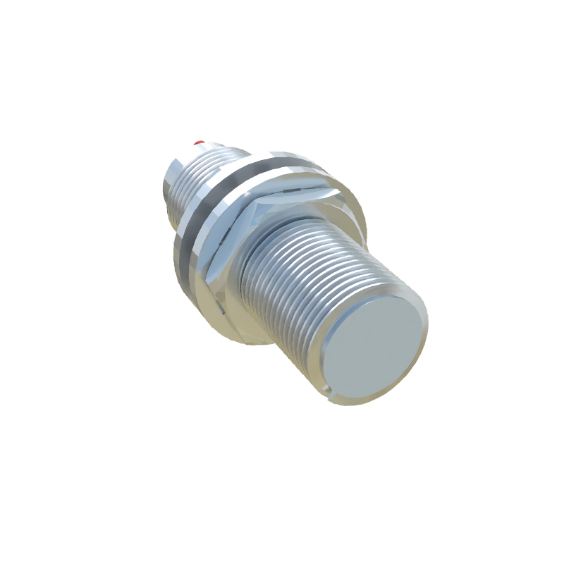
Gathering the correct tools and adhering to safety protocols is non-negotiable. You will need a set of insulated screwdrivers, wire strippers, crimping tools, ferrule terminals, and a digital multimeter. Prior to any work, ensure the main power supply to the control cabinet is locked out and tagged out (LOTO). Verify the absence of voltage using a properly rated voltage tester on the terminals you will be working on. Personal protective equipment (PPE) such as safety glasses and insulated gloves is mandatory. Remember, the DC power supply, typically 10-30V DC for these sensors, must be correctly sized and fused according to the sensor's current consumption and the connected load.
Deciphering the Sensor Datasheet and Nameplate
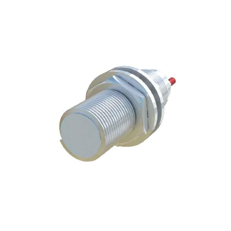
The sensor's nameplate and datasheet are your wiring blueprint. Locate the connection diagram, which will clearly label the wires or terminals. A standard 3-wire sensor will have connections for Brown (L+ or V+), Blue (L- or 0V), and Black (output signal). For a 4-wire sensor, you will often find two output wires (e.g., Black and White) for normally open (NO) and normally closed (NC) contacts. The datasheet specifies the maximum switching current and voltage, leakage current, and short-circuit protection details. Pay close attention to the "Wiring Diagram" section, as it illustrates the complete circuit, including the power supply, sensor, and load (e.g., a PLC input module or a relay coil).
Step-by-Step Wiring Procedure for a 3-Wire DC Sensor
Begin by preparing the cables. Strip the insulation to the appropriate length and crimp ferrule terminals onto the wire ends for a secure and reliable connection in the terminal block. For a PNP sensor, connect the Brown wire to the positive terminal of your DC power supply (e.g., +24V). Connect the Blue wire to the negative terminal (0V or common). The Black output wire is then connected to your load. The other side of the load must be connected back to the 0V common of the power supply. For an NPN sensor, the Brown wire still connects to positive, and the Blue to negative. However, the Black output wire connects to the load, and the other side of the load is connected to the positive supply. This fundamental difference in current flow path is critical for correct operation.
Connecting to a PLC Digital Input Module
Integrating the sensor with a PLC is a common application. First, identify whether your PLC input card is configured for sinking or sourcing input. A sinking input card expects the current to flow into its input terminal. Therefore, you must use a PNP (sourcing) sensor. Connect the sensor's Black wire to the PLC input terminal. The common of the input card is then connected to 0V. Conversely, a sourcing input card expects current to flow out of its input terminal, requiring an NPN (sinking) sensor. Here, the sensor's Black wire connects to the PLC input, and the common of the input card is connected to +24V. Mismatching sensor and input types will result in no signal detection.
Testing and Troubleshooting the Installation
After wiring is complete and double-checked, you can apply power. Use your digital multimeter to verify voltages. Measure between the Brown and Blue wires to confirm the supply voltage (e.g., 24V DC). To test the sensor's operation, bring the target object within its sensing range. For a PNP sensor, you should measure approximately the supply voltage (e.g., 24V) between the Black output wire and the Blue (0V) wire when the target is present. For an N