Understanding Photoelectric Sensor Frequency Fundamentals
The operational frequency of a photoelectric sensor, often referred to as its response frequency or switching frequency, is a critical parameter that determines how quickly the sensor can detect an object and output a corresponding signal. It is typically measured in Hertz (Hz) and defines the maximum number of detection cycles per second. For instance, a sensor with a 1 kHz frequency can theoretically detect up to 1000 objects per second. This specification is paramount in high-speed automation applications, such as packaging lines, sorting systems, or assembly robotics, where precise timing and rapid detection are essential for throughput and accuracy. The frequency is inherently limited by the sensor's internal electronics, the type of light modulation used (e.g., pulsed LED), and the photodetector's response time. Understanding this foundational concept is the first step toward effective frequency adjustment and optimization.
Pre-Adjustment Preparation and System Check
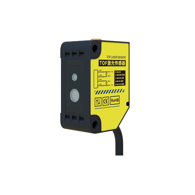
Before attempting to adjust the frequency settings, a thorough system preparation is mandatory. First, ensure the sensor is correctly installed, aligned, and securely mounted. Verify the power supply voltage matches the sensor's specifications to prevent erratic behavior. Inspect the lens for dust, oil, or debris that could attenuate the light beam. For retro-reflective or through-beam sensors, confirm the reflector or receiver is properly aligned. It is also crucial to understand the characteristics of the target object: its size, color, material, surface finish (matte or glossy), and the expected speed of passage. Consult the sensor's datasheet to identify the available adjustment parameters. Many modern photoelectric sensors feature dual functionality: a teach-in mode for sensitivity and a separate parameter, often accessible via a push-button or software, for response time or output delay, which directly influences the effective operational frequency.
Primary Adjustment Methods: Response Time and Hysteresis
Most industrial photoelectric sensors do not have a direct "frequency" knob. Instead, you adjust parameters that govern the sensor's response behavior. The primary control is the Response Time or Output Delay setting. By shortening the response time, you allow the sensor to react faster to changes in the received light signal, thereby enabling a higher switching frequency. However, setting it too short can make the sensor susceptible to electrical noise or brief environmental interferences (like flying debris), causing false triggers. Conversely, a longer response time filters out noise but reduces the maximum detectable frequency. The second key parameter is Hysteresis. Adjusting hysteresis sets the difference between the switch-on and switch-off thresholds. A smaller hysteresis allows the sensor to detect very small objects or precise edges but may cause chattering on unstable signals. A larger hysteresis provides stable switching in noisy environments but requires a more significant change in the signal to toggle the output, potentially limiting effective frequency on rapidly passing small targets.
Optimizing for High-Speed and Special Applications
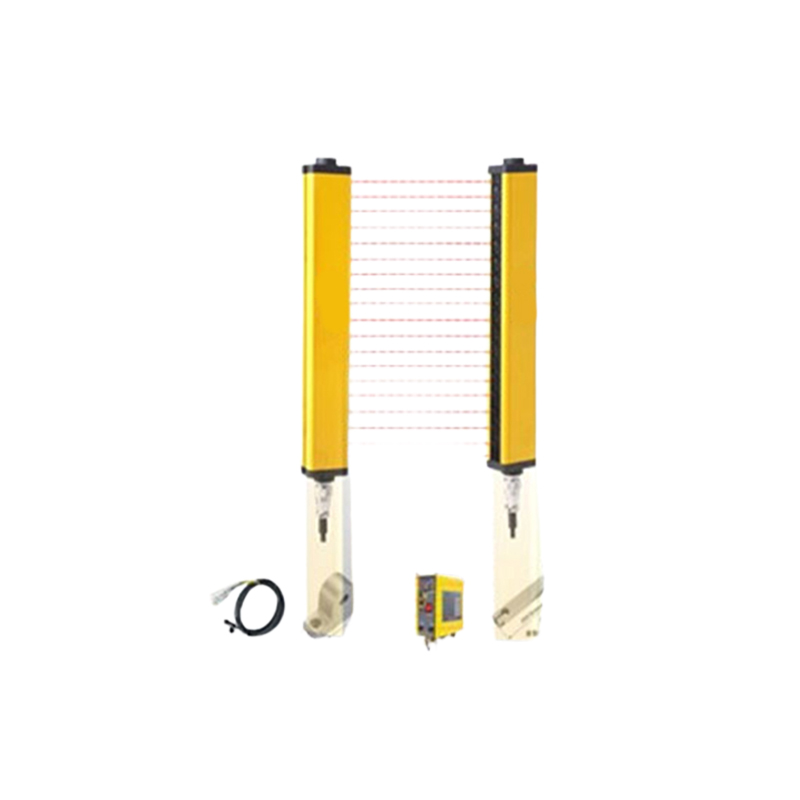
For pushing the sensor to its frequency limits, a targeted optimization strategy is required. Use the Background Suppression function for precise detection independent of color or reflectivity, which can provide a cleaner, faster switching signal. For very small or fast-moving objects, select a sensor with a focused, pinpoint beam. Ensure the operating mode is set correctly: "Light-ON" or "Dark-ON." In some high-speed counting applications, "Dark-ON" (output activates when the beam is broken) can offer a marginal timing advantage depending on the controller's logic. If the sensor has a programmable Output Pulse Width, setting it to the minimum required duration for your PLC or controller to reliably register the signal can prevent pulse elongation that caps effective frequency. Always perform tests with the actual target object at the maximum required speed, monitoring the output with an oscilloscope if possible, to verify clean, square-wave transitions without ringing or delay.
Troubleshooting Common Frequency-Related Issues
If the sensor fails to achieve the desired frequency or exhibits unreliable operation, systematic troubleshooting is necessary. Problem: Missed Counts at High Speed. Likely causes are insufficient response time setting, marginal detection due to low sensitivity (adjust teach-in or sensitivity potentiometer), or the target object being too small for the beam spot at that speed. Problem: False Triggers or Chattering. This often points to an overly short response time, inadequate hysteresis, external light interference (sunlight, welding arcs), or electrical noise on the power supply or output lines. Use shielded cables, ensure proper grounding, and install ferrite cores if needed. Problem: Inconsistent Detection. Check for vibration in the sensor or target mount, fluctuating supply voltage, or condensation on the lens. For sensors with digital communication (IO-Link), verify that the parameter download cycle isn't interfering with the high-speed switching requirement. Always cross-reference the observed behavior with the sensor's published frequency specification to ensure the application demand is within its physical capabilities.
Advanced Configuration via IO-Link and Software
Modern smart photoelectric sensors equipped with IO-Link communication offer unparalleled precision in frequency and parameter adjustment. Through an IO-Link master and configuration software, engineers can access and fine-tune a comprehensive set of parameters far beyond what is available via push-buttons. This includes exact numerical setting of response time (e.g., in microseconds), precise hysteresis levels, filtering algorithms, and sophisticated switching logic (like window mode or counting functions). Parameters can be stored, downloaded to multiple sensors, and even changed on-the-fly based on production recipes. This digital interface also enables continuous monitoring of operating data, such as signal strength or internal temperature, allowing for predictive maintenance and ensuring the sensor maintains its optimal performance and frequency response over time, which is critical in Industry 4.0 environments.