Introduction to Two-Wire Proximity Sensors
Two-wire proximity sensors represent a fundamental and widely adopted design in industrial automation. Unlike their three-wire or four-wire counterparts, these sensors simplify installation by combining the power supply and the switching signal into just two wires. This design directly connects in series with the load, typically a programmable logic controller (PLC) input or a relay coil. The primary appeal lies in reduced wiring costs, easier maintenance, and space savings in control cabinets. They are commonly available in both AC and DC versions, with AC types often used for direct control of contactors or actuators, while DC types are favored for interfacing with modern electronic control systems due to cleaner switching characteristics.
Core Operating Principle
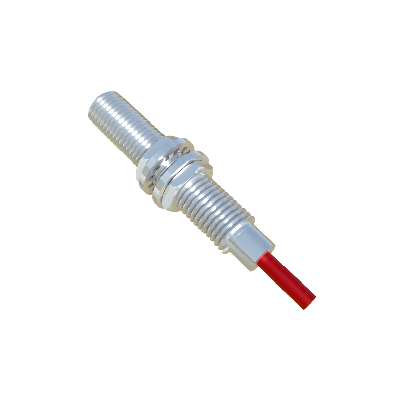
The core functionality hinges on the sensor's internal electronics managing both its own operational power and the switching state through the same two conductors. In the "off" state, a small quiescent current, often called leakage current, flows through the sensor to power its internal oscillator and amplifier circuits. When a target enters the sensing range, the sensor's state changes, allowing a significantly larger current to flow—the "load current"—which is sufficient to energize the connected control device. The key design challenge is ensuring the leakage current is low enough not to accidentally activate the load (preventing "ghost" signals), while the on-state current is high enough to reliably drive it.
Standard Two-Wire DC Circuit Configuration
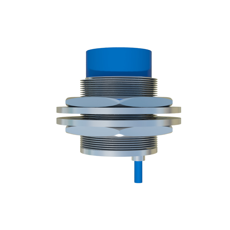
A typical two-wire DC sensor circuit diagram is straightforward. The positive terminal of a DC power supply connects to one wire of the sensor. The sensor's other wire connects to one terminal of the load (e.g., the PLC digital input). The load's other terminal then returns to the negative terminal of the DC supply, completing the series loop. It is crucial to observe polarity; most DC two-wire sensors are polarity-sensitive. A protection diode, often internal, may be present. The load must have a minimum current requirement (hold current) greater than the sensor's off-state leakage current but less than its maximum switching current. A bleeder resistor is sometimes placed in parallel with the load to ensure the leakage current has a path, preventing false triggering on sensitive inputs.
Standard Two-Wire AC Circuit Configuration
For AC operation, the circuit connects similarly in series with the load but uses an AC voltage source, commonly 120VAC or 240VAC. The sensor contains internal circuitry like a bridge rectifier to convert AC to DC for its internal electronics. A critical component in AC two-wire sensors is the snubber network or a solid-state switch like a TRIAC. This manages the switching of the AC waveform. A notable characteristic is a residual voltage drop across the sensor when in the "on" state, which must be accounted for in the load's voltage rating. Wiring is typically not polarity-sensitive. Care must be taken with inductive loads (like contactor coils), as voltage spikes during turn-off can damage the sensor unless protected by internal or external surge suppressors.
Key Design Considerations and Component Selection
Selecting the right components is vital for reliable operation. First, match the sensor's voltage rating (e.g., 10-30VDC, 90-250VAC) precisely with the supply. The load's impedance is critical: its minimum operating current must exceed the sensor's maximum leakage current (specified in datasheets, often<1.5mA for DC). Conversely, the load current when the sensor is on must not exceed the sensor's maximum switching capacity. For long cable runs, voltage drop due to wire resistance can become significant, potentially leaving insufficient voltage at the sensor. In noisy electrical environments, using shielded cables and proper grounding practices is essential to prevent electromagnetic interference from causing erratic switching.
Advantages and Limitations
The advantages of two-wire systems are compelling. They halve the number of wires needed compared to a three-wire PNP/NPN sensor, leading to lower material and labor costs. The simple series connection reduces potential wiring errors. There is no need for a separate neutral wire in AC circuits. However, limitations exist. The leakage current can be problematic for very low-power electronic loads. The voltage drop across the sensor (especially AC types) reduces the voltage available to the load. They generally have lower switching frequencies and slower response times than three-wire DC sensors. Troubleshooting can be slightly more complex, as a fault could be in the sensor, the load, or the wiring.
Practical Application and Troubleshooting Tips
In practice, always consult the manufacturer's datasheet for the specific wiring diagram and electrical characteristics. Use a multimeter to verify the voltage at