Understanding the Photoelectric Upper Limit Switch
In industrial automation, precision and reliability are paramount. The photoelectric sensor upper limit switch stands as a critical component in achieving these goals. Unlike traditional mechanical limit switches that rely on physical contact, photoelectric switches operate on a non-contact principle, using a beam of light to detect the presence or absence of an object. An upper limit switch is specifically configured to monitor a maximum allowable position. When an object, such as a lift platform, robotic arm, or elevator car, reaches this predefined upper boundary, it interrupts the sensor's light beam. This interruption triggers an immediate electrical signal to the control system, halting upward motion to prevent over-travel, collisions, or damage to machinery and infrastructure. This fundamental function is essential for safety and operational integrity across countless applications.
Core Operating Principles and Technologies
The effectiveness of a photoelectric upper limit switch hinges on its underlying technology. The most common configuration for this application is the through-beam (or opposed) mode. This system consists of two separate units: a transmitter that emits a focused beam of light (typically infrared or laser) and a receiver positioned directly opposite. The switch is in its "normal" state when the beam is received uninterrupted. The upper limit is physically set by aligning this beam at the desired stopping point. When the moving object ascends and breaks the beam, the receiver detects the loss of signal, causing the switch to change state and send a stop command. This method offers the longest sensing range and highest reliability, as it is less susceptible to environmental factors like target color, reflectivity, or surface angle, making it ideal for the critical role of an upper limit.
Key Advantages Over Mechanical Alternatives
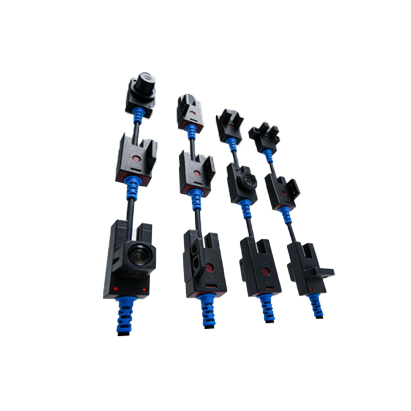
Adopting photoelectric sensors for upper limit control presents significant benefits. First and foremost is the absence of physical wear and tear. Mechanical switches have moving parts that degrade with each actuation, leading to eventual failure. Photoelectric switches, being solid-state, offer exceptionally long service life and maintenance-free operation. Their response time is also vastly superior, measured in microseconds, allowing for high-speed applications and quicker system halts. Furthermore, they provide precise and repeatable detection. The triggering point is defined by the light beam's position, which does not drift over time, ensuring consistent stopping accuracy. This precision is crucial in applications like semiconductor manufacturing or automated warehousing where positional tolerance is minimal.
Critical Selection Criteria for Engineers
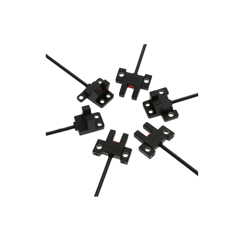
Selecting the appropriate photoelectric upper limit switch requires careful consideration of several technical parameters. Sensing range is primary; the switch must have sufficient range to span the installation gap between transmitter and receiver at the machine's upper extremity. Environmental resistance is equally vital. Enclosures must be rated (e.g., IP67, IP69K) to withstand dust, water jets, and chemical exposure common in industrial settings. The light source type matters: infrared LEDs are common and cost-effective, while laser diodes provide a more precise, collimated beam for long-range or small-target detection. Output configuration must match the control system, typically choosing between NPN/PNP transistor outputs or relay contacts. Finally, engineers must consider auxiliary features like adjustable sensitivity, timing functions, and built-in diagnostics to facilitate setup and troubleshooting.
Typical Industrial Application Scenarios
The application of photoelectric upper limit switches is widespread. In material handling, they secure the top position of automated storage and retrieval systems (AS/RS) and vertical conveyor lifts. In the automotive industry, they prevent robotic welders or painters from exceeding their programmed vertical travel. Elevator and hoist systems rely on them as a primary safety device to prevent the cab from over-traveling at the top floor. Packaging machinery uses them to ensure carton erectors or filling heads do not rise beyond a safe point. Even in renewable energy, they monitor the maximum tilt angle of solar panel tracking systems. In each case, the switch acts as a fail-safe, providing a hardwired signal independent of the primary motion controller for enhanced safety.
Installation Best Practices and Alignment
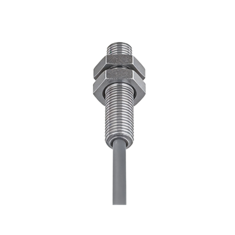
Proper installation is critical for reliable operation. The transmitter and receiver must be mounted on stable, vibration-resistant surfaces to prevent misalignment. For through-beam sensors, precise optical alignment is mandatory. Using an alignment tool or the sensor's built-in signal strength indicator during setup is recommended. The sensing beam should be positioned so that the target will cleanly interrupt it without grazing or partial blockage. It is often advisable to install the switch in a slightly recessed or protected location to shield the lens from accumulating dirt, debris, or direct impact. Wiring should follow EMC guidelines, using shielded cables in high-noise environments and ensuring secure connections to prevent signal dropouts that could be misinterpreted as a limit trigger.
Integration with Control Systems and Safety
The output from a photoelectric upper limit switch is typically integrated into a machine's safety circuit or directly into the programmable logic controller (PLC). For safety-critical applications, it is common practice to use the switch in a normally closed (NC) safety circuit. In this configuration, a broken wire or sensor failure causes the circuit to open, initiating a safe stop—a principle known as "fail-safe." Redundant systems, employing two independently mounted switches (one for primary limit and one as an ultimate over-travel backup), are often mandated by safety standards like ISO 13849. The switch's signal can also be used for non-safety operational logic, such as initiating the next phase of a cycle once the upper limit is confirmed.
Maintenance, Diagnostics, and Troubleshooting
While largely maintenance-free, periodic inspection ensures ongoing reliability. The primary maintenance task is keeping the optical lenses clean from dust, oil film, or condensation, which can attenuate the light beam and reduce effective range. Most modern sensors feature LED status indicators that provide immediate diagnostic information: a green LED often indicates power, while a yellow or red LED shows output state or signal strength. A common troubleshooting issue is false triggering or failure to trigger. This can stem from misalignment due to vibration, lens contamination, electrical interference, or an incorrect sensing range for the application. Methodically checking alignment, cleaning lenses, and verifying the sensor's signal strength under operating conditions usually resolves these issues.