Introduction to Photoelectric Sensors
Photoelectric sensors are widely used in industrial automation for detecting objects, counting, and positioning. They operate by emitting a light beam and measuring the reflection or interruption. While commercial sensors are readily available, building a simple DIY version can be a rewarding project for engineers and hobbyists. This guide provides a step-by-step approach to creating a basic photoelectric sensor using common electronic components. The design focuses on simplicity, cost-effectiveness, and educational value, making it suitable for prototyping or learning purposes. Understanding the principles behind these sensors enhances practical skills in circuit design and signal processing.
Required Components and Tools
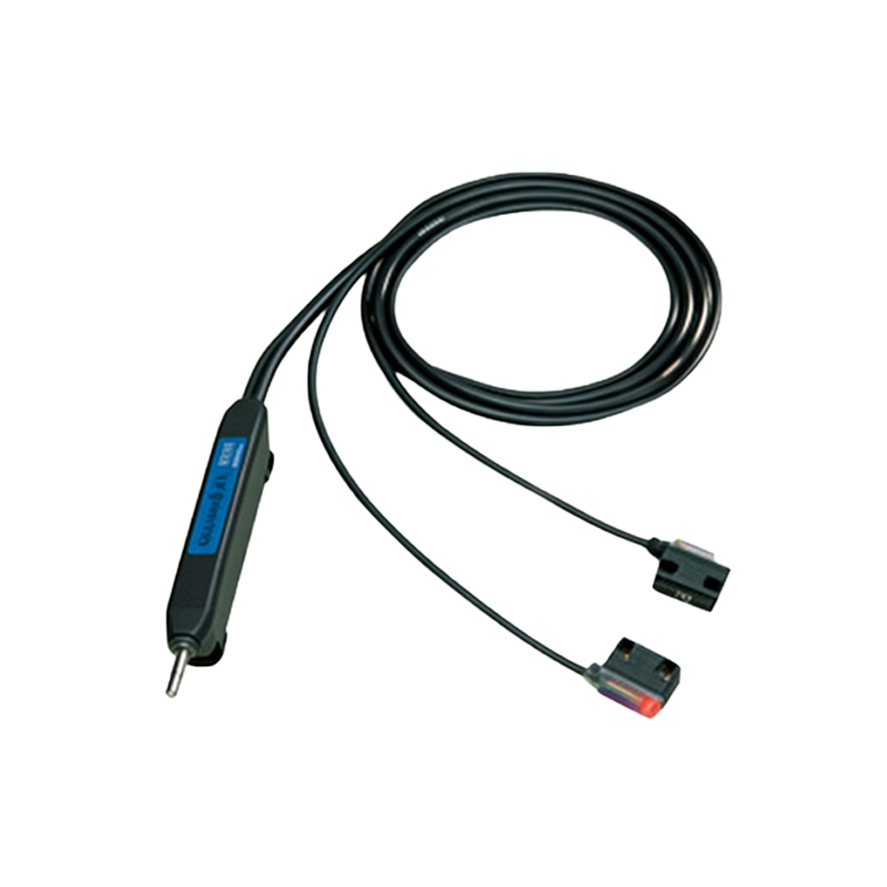
To build a DIY photoelectric sensor, gather the following components: an infrared (IR) LED, a phototransistor or photodiode, resistors (e.g., 220Ω and 10kΩ), a breadboard, jumper wires, a power supply (e.g., 5V DC), and an optional operational amplifier (op-amp) like LM358 for signal amplification. Basic tools include a multimeter, soldering iron, and wire cutters. Choose an IR LED and phototransistor with matching wavelengths for optimal performance. The phototransistor acts as the receiver, converting light intensity into electrical current. Ensure all parts are compatible to avoid circuit issues.
Circuit Design and Assembly
Start by constructing the transmitter circuit: connect the IR LED in series with a 220Ω resistor to limit current, then link it to the power supply's positive and negative terminals. For the receiver, place the phototransistor in series with a 10kΩ pull-up resistor between the supply voltage and ground. The output signal is taken from the junction between the phototransistor and resistor. Assemble the circuits on a breadboard for easy testing. Keep the IR LED and phototransistor aligned but separated to prevent direct coupling. Use an op-amp if the output signal is weak; configure it as a comparator to switch states based on light changes.
Calibration and Testing Procedures
After assembly, power the circuit and use a multimeter to measure the output voltage. In ambient light, the phototransistor should conduct, producing a low voltage output. When an object interrupts the IR beam, the voltage should rise. Adjust the resistor values to fine-tune sensitivity; for instance, increase the pull-up resistor for higher gain. Test the sensor by moving objects at different distances and speeds. Record the response time and detection range. If using an op-amp, set the reference voltage with a potentiometer to trigger at desired light levels. Ensure stable operation under varying lighting conditions.
Applications and Practical Tips
This DIY sensor can be used in simple automation projects, such as object detection on conveyor belts, door sensors, or counting systems. For improved performance, shield the sensor from external light interference using enclosures or tubes. Consider adding a microcontroller like Arduino for digital processing and connectivity. Regularly clean the IR LED and phototransistor lenses to maintain accuracy. Experiment with different configurations, such as reflective or through-beam setups, to suit specific needs. Always follow safety guidelines when working with electrical components to prevent shorts or overheating.
Conclusion and Further Enhancements
Building a DIY photoelectric sensor is an excellent way to grasp fundamental concepts in optoelectronics and automation. This project demonstrates how basic components can create functional devices. For advanced versions, integrate modulated IR signals to reduce ambient light effects, or use laser diodes for longer ranges. Explore online resources and communities for shared designs and troubleshooting. By mastering this skill, engineers can customize sensors for unique applications, fostering innovation in fields like robotics and IoT. Keep experimenting to refine your designs and expand technical expertise.