Understanding NPN Proximity Sensors
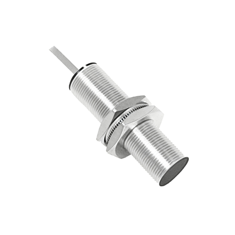
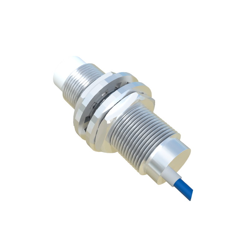
An NPN proximity sensor is a widely used industrial device that detects the presence or absence of a metallic object without physical contact. It operates on the principle of electromagnetic induction or capacitive sensing. The term "NPN" refers to the type of transistor output it employs. In an NPN sensor, the output acts as a switching device that sinks current to the common ground (0V) when activated. This means the sensor's output terminal is connected to the load, which in turn is connected to the positive voltage supply. When a target object enters the sensor's detection range, the internal transistor switches on, allowing current to flow from the load through the sensor to ground, thereby signaling detection. Understanding this sinking behavior is crucial for correct integration with Programmable Logic Controllers (PLCs), as it dictates the wiring and input configuration.
PLC Digital Input Module Basics
Most PLCs are equipped with digital input modules designed to receive signals from field devices like sensors and switches. These modules typically have two common wiring types: sinking and sourcing. A sinking input module has its common terminal connected to the positive voltage supply (e.g., +24V DC), expecting current to flow into the input point from the connected device. Conversely, a sourcing input module has its common terminal connected to ground (0V), expecting current to flow out of the input point to the connected device. For an NPN proximity sensor, which sinks current, it is naturally compatible with a sourcing-type PLC input module. Mismatching the sensor type with the input module can lead to malfunction or damage, so verifying the PLC input specifications is an essential first step before connection.
Wiring Configuration and Steps
The physical connection involves three main wires from the NPN proximity sensor: brown (typically for positive supply), blue (for ground or 0V), and black (for the output signal). First, ensure the power supply matches the sensor's voltage rating, commonly 10-30V DC. Connect the brown wire to the positive terminal of the DC power supply and the blue wire to the negative terminal (0V). Next, identify a sourcing input point on the PLC's digital input module. Connect the black output wire from the sensor to the chosen input terminal (e.g., I0.0). Then, connect the common terminal (often labeled as COM or M) of the PLC input module to the positive side of the same DC power supply. This setup completes the circuit: when the sensor detects an object, current flows from the PLC input point, through the sensor's output transistor, to ground, activating the PLC input. Always use shielded cables for noise reduction and secure connections to prevent intermittent faults.
PLC Programming and Input Addressing
After wiring, the PLC must be programmed to recognize the sensor's signal. Using the PLC's software (such as TIA Portal for Siemens, RSLogix for Allen-Bradley, or GX Works for Mitsubishi), configure the input address corresponding to the physical terminal used. For instance, if the sensor is wired to terminal I0.0, this address will be referenced in the ladder logic or function block diagram. Typically, no special configuration is needed for a basic digital input; the PLC will read the state as TRUE or ON when the sensor is active (object detected), and FALSE or OFF otherwise. You can then use this input to trigger actions, such as starting a motor, incrementing a counter, or activating an output. It's advisable to include debounce logic in the program to filter out electrical noise or brief false triggers, ensuring reliable operation in industrial environments.
Troubleshooting Common Issues
Several problems may arise when connecting an NPN sensor to a PLC. If the PLC input does not activate, first check the power supply to both the sensor and the PLC module, ensuring voltage levels are correct. Verify the wiring: confirm the sensor's output is connected to the PLC input and the PLC common is connected to positive supply. Use a multimeter to measure the sensor's output voltage relative to ground; it should switch from high (near supply voltage) to low (near 0V) when activated. If the input flickers erratically, consider electrical interference and ensure proper grounding and cable shielding. Additionally, check the sensor's sensing range and alignment with the target object, as mechanical misalignment can cause detection failures. Consulting the sensor and PLC manuals for specific diagnostics is always recommended for persistent issues.
Safety and Best Practices
Safety is paramount in industrial automation. Always disconnect power before making or modifying connections to prevent electric shock or equipment damage. Use appropriately rated components, such as fuses or circuit breakers,