Understanding Inductive Proximity Sensors
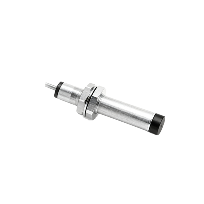
Inductive proximity sensors are widely used in industrial automation for non-contact detection of metallic objects. These sensors operate based on the principle of electromagnetic induction, where an oscillator generates a high-frequency magnetic field. When a metal target enters this field, eddy currents are induced, causing a change in the oscillator's amplitude. This change is detected by the sensor's circuitry, triggering an output signal. Common applications include position sensing, object counting, and machine safety systems. Their robustness, reliability, and ability to function in harsh environments make them essential components in manufacturing, packaging, and automotive industries.
Key Components of Wiring Diagrams
A standard inductive proximity sensor wiring diagram includes several critical components. The sensor itself typically has three or four wires: brown (positive supply), blue (negative or ground), black (output signal), and sometimes white (complementary output or diagnostic). The power supply, usually 10-30V DC, connects to the brown and blue wires. The output wire (black) links to the load, such as a PLC input, relay, or indicator. Diagrams also depict shielding, cable types, and connection points to controllers. Understanding these elements ensures correct installation, preventing issues like short circuits or sensor damage.
Two-Wire vs. Three-Wire vs. Four-Wire Configurations
Inductive proximity sensors come in different wiring configurations. Two-wire sensors are simple, with one wire for power and the other for load connection, but they may have higher leakage current. Three-wire sensors are more common, offering separate power and output wires for better performance and lower interference. Four-wire sensors provide dual outputs (e.g., normally open and normally closed) or diagnostic features for advanced control. Diagrams for each type show distinct connections: for three-wire, brown to positive, blue to negative, and black to load; for four-wire, additional wires like white for secondary functions. Selecting the right configuration depends on application needs and system compatibility.
Step-by-Step Wiring Instructions
To wire an inductive proximity sensor, start by disconnecting power to avoid electrical hazards. Identify the sensor's wires using the manufacturer's datasheet—typically brown for positive, blue for negative, and black for output. Connect the brown wire to the positive terminal of the DC power supply (e.g., 24V) and the blue wire to the negative terminal. Link the black output wire to the input of the control device, such as a PLC, ensuring proper grounding. Use shielded cables in noisy environments to reduce electromagnetic interference. After connections, secure wires with cable glands and test the sensor with a metal target to verify operation. Always follow local electrical codes and safety standards.
Common Wiring Mistakes and Troubleshooting
Errors in wiring can lead to sensor failure or system malfunctions. Common mistakes include reversing power polarity, which may damage the sensor, or incorrect load connections causing no output. Ensure the power supply voltage matches the sensor rating (e.g., 12-24V DC). If the sensor doesn't detect targets, check for loose wires, insufficient voltage, or metal debris interfering with the sensing face. Use a multimeter to measure voltage at the output wire; it should switch between high and low states when a target is present. Refer to the wiring diagram for correct terminal assignments and consult manufacturer guidelines for specific troubleshooting steps.
Applications and Best Practices
Inductive proximity sensors are versatile in industrial settings. In conveyor systems, they detect metal parts for counting or sorting. In robotics, they ensure precise positioning of arms. For optimal performance, mount sensors securely, avoiding vibration or misalignment. Maintain a clean sensing area free from oil, dust, or other metals that could cause false triggers. Choose sensors with appropriate sensing ranges and housing materials (e.g., stainless steel for corrosive environments). Regularly inspect wiring for wear and update diagrams as systems expand. Integrating these sensors with PLCs or HMIs enhances automation efficiency and safety.
Conclusion and Resources
Proper wiring of inductive proximity sensors is crucial for reliable operation in automation systems. By understanding wiring diagrams, configurations, and installation steps, engineers can avoid common pitfalls and ensure longevity. Always use high-quality components and adhere to industry standards like IEC 60947-5-2 for sensor specifications. For further details, refer to manufacturer manuals, online tutorials, or professional training courses. Keeping diagrams updated and documenting changes aids in maintenance and troubleshooting, supporting seamless industrial processes.