Understanding Photoelectric Sensor Overflow High
In industrial automation, a "Photoelectric Sensor Overflow High" alarm or signal indicates a condition where the received light intensity at the sensor's receiver is significantly beyond its designed operational range. This is not merely a strong signal; it represents a saturation state where the photodetector is overwhelmed, often leading to a failure in proper object detection or distance measurement. Unlike a simple "object detected" state, an overflow condition can cause the sensor to behave erratically, potentially interpreting the excessive light as an absence of an object or providing unstable output. This phenomenon is critical to address, as it directly impacts the reliability of automated processes, from packaging lines to robotic assembly cells, where consistent and accurate sensing is paramount for efficiency and safety.
Primary Causes of Light Saturation
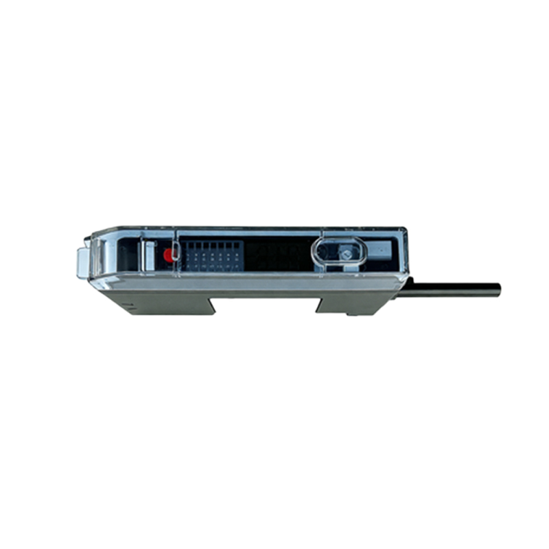
Several factors can lead to this overflow condition. The most common cause is external ambient light interference. Powerful sources like direct sunlight, unshielded high-intensity discharge (HID) lamps, or welding arcs can flood the sensor's receiver with photons, overwhelming its intended modulated light signal. Another frequent cause is improper installation or alignment in reflective sensing modes. When a retro-reflective or diffuse sensor is positioned too close to a highly reflective target or background, the returning light beam can be much stronger than anticipated. Additionally, internal component failure, such as a degraded or contaminated lens on the emitter side, can sometimes cause irregular light dispersion that unexpectedly concentrates on the receiver. Using a sensor with an incompatible sensing range for the application also poses a risk; for instance, employing a precise, short-range sensor for a task requiring long-distance detection might lead to saturation when a reflective object enters its near field.
Diagnostic Procedures and Troubleshooting Steps
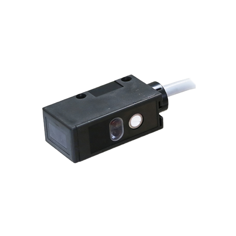
Systematic diagnosis is key to resolving an overflow high issue. Begin by observing the environmental conditions. Monitor for intermittent alarms correlated with specific events, such as sunlight passing through a window or the activation of nearby machinery with bright lights. Physically inspect the sensor and its lens for dust, oil mist, or condensation that could cause internal reflections. Use the sensor's built-in indicators, if available; many modern sensors have dual LEDs showing both power and output/overflow status. Next, perform an alignment check. For retro-reflective sensors, ensure the alignment with the reflector is precise and that the reflector itself is clean. For diffuse sensors, try increasing the distance to the target or adjusting the angle of incidence. A highly effective diagnostic tool is to temporarily shield the sensor from all ambient light using an opaque material. If the overflow condition clears, ambient light is confirmed as the culprit. Finally, verify the electrical connections and supply voltage, as rare power surges or noise can sometimes mimic sensor faults.
Effective Mitigation and Correction Strategies
Once the root cause is identified, implement corrective measures. To combat ambient light, select sensors with robust background suppression technology or modulated light operation (often pulsed LED) that ignores constant light sources. Installing physical barriers, shrouds, or tubular housings around the sensor can block stray light. Adjusting the sensor's mounting angle or location is a simple yet often effective solution. For issues related to highly reflective targets, consider switching the sensing mode. Using a polarized retro-reflective sensor can reject light reflected directly from shiny objects. Alternatively, a diffuse sensor with background suppression or a convergent beam mode can precisely define a sensing window, ignoring reflections from outside that zone. If the sensor's range is inappropriate, recalibrate its sensitivity potentiometer (if present) to a lower setting or replace it with a model better suited to the required operating distance and target reflectivity.
Selection and Preventive Best Practices
Preventing overflow conditions begins with proper sensor selection and system design. Always specify sensors with features designed for challenging environments. Look for high ambient light immunity ratings, typically expressed in lux (e.g., immunity up to 10,000 lux). Fiber optic sensors, with their small apertures and flexible positioning, can often be routed away from light interference. During installation, meticulously follow the manufacturer's guidelines for alignment, sensing distance, and mounting. Establish a routine preventive maintenance schedule that includes cleaning optical components with appropriate materials and checking for physical misalignment due to vibration. For critical applications, consider implementing a system health monitoring routine that logs sensor signal strength, allowing for predictive maintenance before an overflow fault disrupts production. By integrating these considerations from the design phase through ongoing operation, engineers can ensure photoelectric sensors deliver maximum uptime and reliability, free from the disruptions caused by overflow high conditions.