Understanding Photoelectric Sensors and Their Types
Photoelectric sensors are widely used in industrial automation for detecting the presence, absence, or distance of objects without physical contact. These sensors operate by emitting a light beam—typically infrared, visible, or laser—and measuring the reflected or interrupted light. There are three main types: through-beam, retro-reflective, and diffuse reflective sensors. Through-beam sensors consist of separate emitter and receiver units, offering long-range detection. Retro-reflective sensors use a reflector to bounce light back to the receiver, suitable for medium-range applications. Diffuse reflective sensors have the emitter and receiver in one housing, detecting objects based on light reflection, ideal for short-range tasks. Understanding these types is crucial for selecting the right sensor for Arduino-based projects in industrial settings, such as conveyor belt monitoring or object counting.
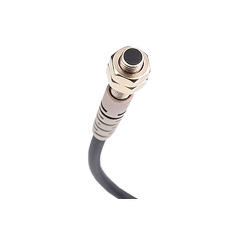
Components Required for Arduino and Sensor Integration
To connect a photoelectric sensor to an Arduino, you will need specific components. First, an Arduino board, such as the Arduino Uno or Mega, serves as the microcontroller. Next, choose a compatible photoelectric sensor—common models include the E18-D80NK (diffuse reflective) or the TCRT5000 (infrared reflective). Additionally, gather jumper wires for connections, a breadboard for prototyping, and resistors (e.g., 10kΩ pull-up resistors) if required by the sensor. For power, the Arduino can supply 5V DC, but some industrial sensors may need external power sources. A multimeter is helpful for testing voltage levels. Ensure all components match the sensor's voltage and current specifications to avoid damage. This setup forms the foundation for reliable detection systems in automation projects.
Wiring the Photoelectric Sensor to the Arduino Board
Proper wiring is essential for accurate sensor operation. Start by identifying the sensor's pins: typically, VCC (power), GND (ground), and OUT (signal output). Connect the VCC pin to the Arduino's 5V pin, and the GND pin to the Arduino's GND pin. For the OUT pin, link it to a digital input pin on the Arduino, such as pin 2 or 3. If using a sensor with analog output, connect it to an analog input pin like A0. In some cases, add a pull-up resistor between the OUT pin and VCC to stabilize the signal. Double-check connections to prevent short circuits. For through-beam sensors, wire the emitter and receiver separately, ensuring correct polarity. This step ensures the Arduino can read sensor data effectively for processing.
Programming the Arduino for Sensor Data Reading
Once wired, program the Arduino to interpret sensor signals. Use the Arduino IDE to write a sketch. Begin by declaring the sensor pin as an input in the setup function. For digital sensors, use digitalRead() to detect high or low states, indicating object presence. For analog sensors, use analogRead() to measure voltage levels, which can correlate with distance or reflectivity. Include serial communication (Serial.begin(9600)) to monitor readings on a computer. For example, a simple code might trigger an LED when an object is detected. Advanced programming can involve calibrating thresholds, filtering noise, or integrating with other devices via protocols like I2C. Test the code by uploading it to the Arduino and observing serial output for accuracy.
Calibrating and Testing the Sensor System
Calibration ensures reliable performance in industrial environments. Start by placing the sensor at the desired distance from the target object. Adjust sensitivity settings if the sensor has a potentiometer. Use the serial monitor to observe signal values and set appropriate thresholds in the code. Test under various conditions, such as different lighting or object materials, to account for interference. For diffuse sensors, ensure the object reflects sufficient light. For through-beam sensors, align the emitter and receiver precisely. Perform repeated trials to check consistency, and use debugging tools like oscilloscopes if needed. Calibration minimizes false triggers and enhances system robustness, critical for applications like automated assembly lines.
Industrial Applications and Best Practices
Arduino-connected photoelectric sensors are versatile in industrial automation. Common applications include object detection on conveyor belts, liquid level sensing in tanks, and safety systems for machinery. To ensure success, follow best practices: shield sensors from ambient light interference using enclosures, maintain clean lenses to prevent dust buildup, and use shielded cables to reduce electrical noise. Regularly inspect connections for wear and update firmware as needed. Integrate fail-safes, such as redundant sensors, for high-stakes operations. Document wiring diagrams and code for maintenance. By adhering to these practices, engineers can build durable and efficient systems that meet industrial standards, leveraging Arduino's flexibility for cost-effective solutions.