Understanding Proximity Sensor Module Fundamentals
Proximity sensor modules are integral components in modern industrial automation, providing non-contact detection of metallic or other specific objects. These modules typically consist of a sensor head and a separate amplifier or controller unit. The sensor head generates an electromagnetic field or emits a beam of light, depending on the type—inductive, capacitive, or photoelectric. The module's amplifier processes the signal from the sensor head, converting the detection event into a clear, usable output signal, usually a switching signal. Understanding this basic two-part architecture is crucial before attempting any wiring, as it dictates the connection points and requirements. The module's housing contains terminals or connectors for power supply, output signals, and sometimes auxiliary functions like teach-in or diagnostics. Always refer to the manufacturer's specific datasheet, as pin configurations and functions can vary significantly between models and brands, even within the same sensing technology family.
Standard Wiring Configuration and Terminal Identification
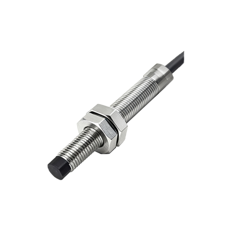
A standard three-wire DC proximity sensor module is the most common configuration in industrial settings. The terminals are typically labeled as follows: Brown wire or terminal for DC positive supply voltage (V+ or +V), Blue wire or terminal for DC common or negative supply (0V or COM), and Black wire or terminal for the load output signal. For a normally open (NO) output module, the black wire provides a switched positive voltage when a target is detected. Some modules may have a white wire for a complementary normally closed (NC) output or for other functions. The first step in wiring is to correctly identify these terminals on your specific module. Many modules feature clear embossed labeling next to screw terminals or a diagram on the housing. For connector types, the mating connector's pinout must be followed precisely. Incorrect power polarity connection is a common cause of immediate failure, so double-checking the brown (positive) and blue (negative/ common) connections against your power source is a non-negotiable safety and operational step.
Power Supply Connection and Considerations
Connecting a stable and appropriate power supply is critical for reliable sensor operation. Most industrial DC proximity sensor modules operate within a range of 10-30V DC. Ensure your power supply voltage falls within the specified range on the module's nameplate. The power supply must be capable of delivering the required current, which is typically low (often below 200mA). Connect the brown wire to the positive (+) terminal of your DC power supply and the blue wire to the negative (-) or 0V terminal. It is highly recommended to use a fused and, if possible, regulated power supply to protect the sensor from voltage spikes and noise prevalent in industrial environments. For installations involving multiple sensors, a common power distribution system can be used, but ensure the total current draw does not exceed the power supply's capacity. Always implement proper grounding practices. While the blue wire is the common return, the metal housing of the sensor, if present, should also be grounded to the machine chassis or earth ground to shield against electromagnetic interference (EMI).
Output Signal Wiring to the Load
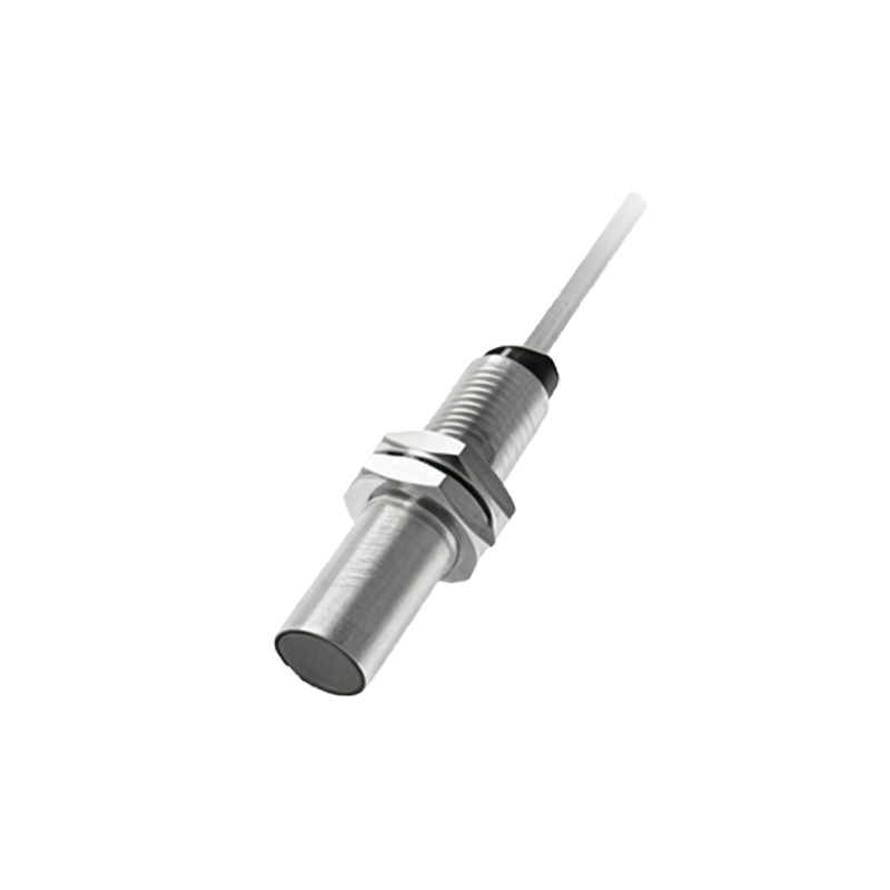
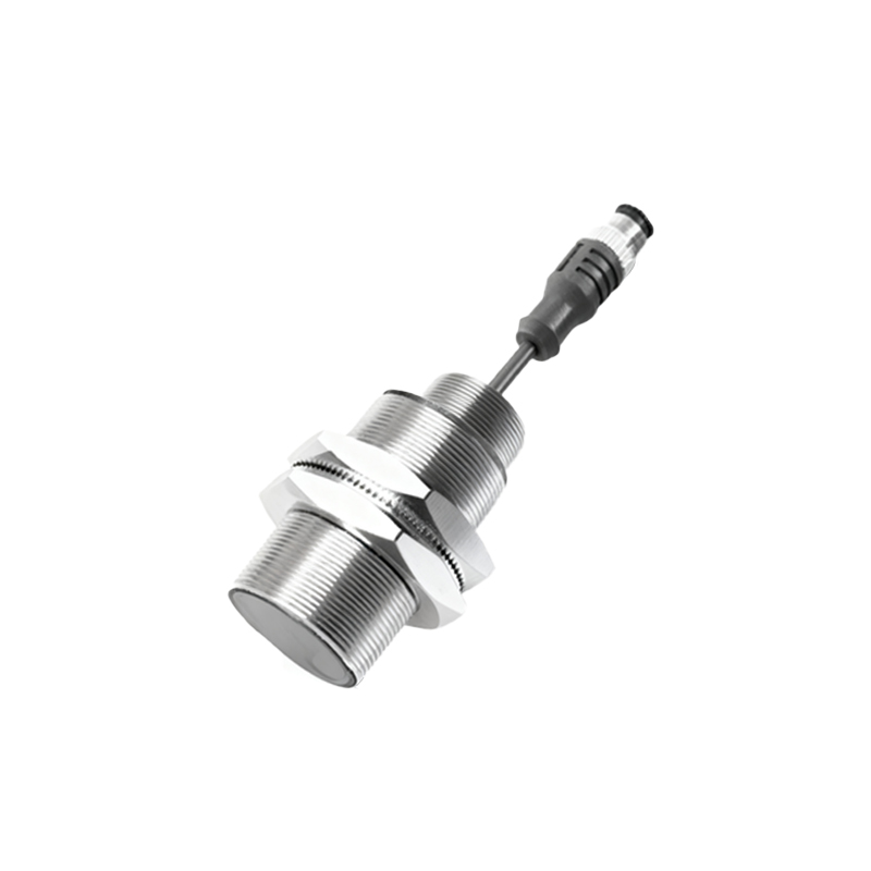
The output terminal (usually black wire) is connected to the device you wish to control, known as the load. This load is most commonly the input of a Programmable Logic Controller (PLC), a relay coil, or an indicator lamp. For a standard NPN (sinking) output module, the black wire acts as a switched negative. When the sensor detects an object, it connects the black output terminal internally to the blue (0V) terminal, allowing current to sink from the load into the sensor. The load must be connected between the positive supply (V+) and the black wire. Conversely, for a PNP (sourcing) output module, the black wire acts as a switched positive. Upon detection, it connects the black terminal to the brown (V+) internally, sourcing current to the load. The load is then connected between the black wire and the common (0V). Mismatching NPN and PNP wiring with the receiving device (like a PLC input) will result in no operation. Always verify your module's output type (NPN or PNP) and wire the load accordingly.
Wiring for Two-Wire AC/DC Sensors
Two-wire proximity sensor modules simplify wiring by combining the power supply and load connections into two wires. They are connected in series with the load and the power supply. These modules can often work with both AC and DC voltages. For a two-wire DC sensor, one wire connects to the positive side of the power supply, and the other wire connects to one side of the load; the other side of the load then connects back to the negative side of the supply, completing the series