Understanding Photoelectric Sensor Wiring Fundamentals
Photoelectric sensors are ubiquitous in industrial automation for detecting the presence, absence, or distance of objects without physical contact. Their reliable operation hinges on correct wiring, which varies based on the sensor's output type and power requirements. The core principle involves connecting the sensor to a power source and linking its output signal to a control device, such as a Programmable Logic Controller (PLC), relay, or counter. Before handling any wires, always consult the specific sensor's datasheet for its electrical characteristics, terminal designations, and wiring diagrams. Safety is paramount; ensure all power is locked out and tagged out (LOTO) before beginning installation to prevent electrical shock or equipment damage. The most common configurations involve 3-wire and 4-wire sensors, though 2-wire versions also exist for simpler applications.
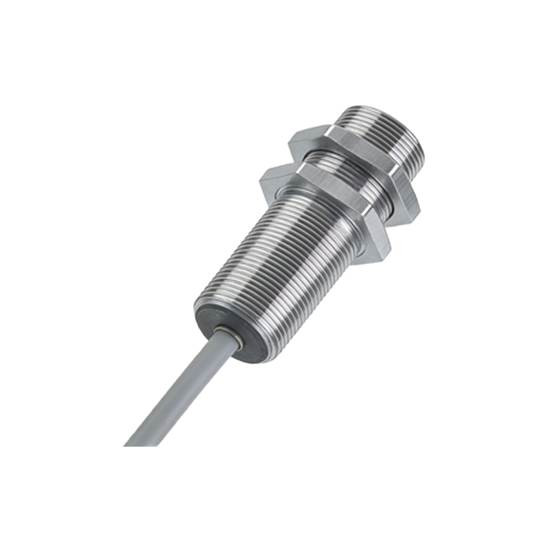
Decoding Wire Color Standards and Functions
While colors can vary by manufacturer, a widely accepted standard exists for DC sensors. For a 3-wire DC sensor, you will typically find a brown wire, a blue wire, and a black wire. The brown wire is the positive supply voltage lead (+V). This connects to the positive terminal of your DC power source, commonly 12-24 VDC. The blue wire is the negative supply voltage lead (0V or common). This connects to the negative terminal of the DC power source. The black wire is the output signal wire. Its behavior depends on the sensor's output type. In a sinking (NPN) output sensor, the black wire provides a path to 0V when active. In a sourcing (PNP) output sensor, the black wire provides a path to +V when active. A 4-wire DC sensor adds a second output wire, usually white, providing both a normally open (NO) and a normally closed (NC) signal from the same unit.
Wiring a 3-Wire DC Sinking (NPN) Sensor
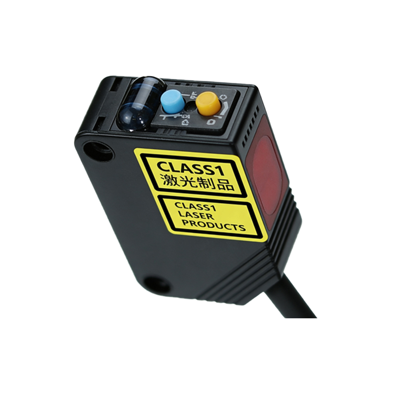
To wire a 3-wire NPN sensor, first connect the brown wire to the positive side of your 24 VDC power supply. Connect the blue wire to the negative side of the same power supply. The critical connection is the black output wire. For an NPN sensor, the output acts as a switch to ground. Therefore, the load (e.g., a PLC input module) must be connected between the positive supply and the black wire. One side of the PLC input is connected to +V (often labeled +24V), and the other side is connected to the sensor's black wire. When the sensor detects an object, it closes an internal switch, connecting the black wire to 0V (blue wire), completing the circuit and allowing current to flow into the PLC input, signaling an "ON" state. This is called a sinking input configuration because the sensor sinks current into itself.
Wiring a 3-Wire DC Sourcing (PNP) Sensor
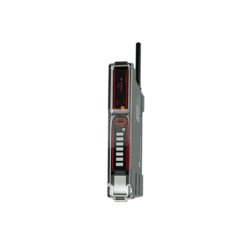
Wiring a 3-wire PNP sensor follows a similar but opposite logic. Again, connect brown to +V and blue to 0V. For the PNP output, the black wire acts as a switch to the positive voltage. The load (PLC input) must now be connected between the black wire and the 0V (common). Connect one side of the PLC input to the sensor's black wire and the other side to the 0V (blue wire/common). When the sensor activates, it switches the black wire to +V, providing a positive voltage signal to the PLC input, completing the circuit to common. This is a sourcing output because the sensor sources current from the positive supply. Mismatching NPN and PNP wiring with the controller will result in no signal transmission.
Connecting to AC Powered Photoelectric Sensors
AC sensors, often used in higher power applications or legacy systems, typically have two or four wires. A basic 2-wire AC sensor is wired in series with the load and the AC power source (e.g., 120 VAC). One wire connects to the hot (L) side of the AC source, and the other connects to one side of the load; the load's other side connects to the neutral (N). The sensor controls the current flow through itself. A 4-wire AC sensor has two separate pairs: a pair for the power supply (L1 and N) and a pair for the output switch (typically relay contacts). The output contacts are isolated and can be used to switch a separate load circuit, which can be AC or DC, providing greater flexibility.
Integrating with PLCs and Control Systems
Successful integration requires matching the sensor's output type with the PLC input type. Modern PLCs often have input cards that can be configured for either sinking or sourcing, but the wiring must be consistent. For a sinking (NPN) sensor, the PLC input module must be wired as a sourcing input. For a sourcing (PNP) sensor, the PLC input must be wired as a sinking input. This complementary relationship ensures a complete circuit. Always verify the voltage ratings. A 24 VDC sensor should connect to a 24 VDC PLC input. Incorrect voltage can damage components. For reliable operation in electrically noisy environments, use shielded cable for the sensor wires, connect the shield to ground at one end only (typically the control panel end), and keep sensor cables away from power lines and motor drives.
Troubleshooting Common Wiring Issues
If a sensor fails to operate, follow a logical diagnostic process. First, verify power is present at the sensor terminals (between brown and blue for DC) using a multimeter. Next, check the output signal. Actuate the sensor and measure the voltage between the black wire and blue wire (for NPN) or black wire and brown wire (for PNP). You should see a voltage change corresponding to the sensor's state. If the sensor has an indicator LED, observe its behavior. A solid LED with no output change often points to a wiring error between the output and the load or a mismatch between sensor output type and load type. Ensure no wires are loose, frayed, or shorted. Remember, a correctly wired sensor is the foundation for robust and maintenance-free automation.