Introduction to Proximity Switch PCB Markings
Printed Circuit Boards (PCBs) are the fundamental backbone of modern proximity switch sensors. The various markings found on these PCBs serve as a critical communication tool between the manufacturer, the engineer, and the technician. These identifiers are not merely decorative; they provide essential information regarding the sensor's type, electrical characteristics, pin configuration, and compliance standards. Understanding these markings is paramount for correct installation, troubleshooting, and system integration. This guide delves into the common and specialized markings encountered on proximity sensor PCBs, translating the silkscreen language into actionable engineering knowledge.
Component Designators and Reference Designators
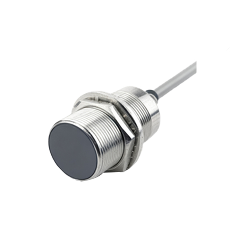
The most ubiquitous markings are component designators, typically consisting of an alphabetical letter followed by a number. These are standardized references that identify each component's type and its specific location on the board. For instance, 'R1', 'R2' denote resistors; 'C1', 'C2' indicate capacitors; 'D1' is a diode; 'Q1' or 'T1' often label transistors; and 'U1', 'IC1' refer to integrated circuits. In proximity sensors, special attention should be paid to components like 'L1', which may indicate the sensing coil or oscillator inductor core to the sensing element. The bill of materials (BOM) for the assembly uses these exact designators, making them the primary key for schematic cross-referencing and part replacement.
Pin Numbering and Functional Labels
Proximity sensors commonly have three or four connection pins. The PCB will clearly mark these, often as '1', '2', '3', '4' or with functional abbreviations near the terminal block or wire solder points. Standard functional labels include:
- V+ or +Vs: Positive supply voltage terminal.
- 0V, GND, or COM: Common ground or negative supply terminal.
- OUT: The switched output signal. This may be further qualified as 'NO' (Normally Open) or 'NC' (Normally Closed) for mechanical relay output types, or simply as 'OUT' for solid-state PNP or NPN transistors.
- SHIELD or SH: Connection point for the cable shield, crucial for noise immunity in inductive and capacitive sensors.
For programmable or configurable sensors, additional pins like 'IN' (input for teach-in) or 'M' (mode) might be present. Always verify these against the sensor's datasheet, as the pinout can vary between manufacturers and output types (sourcing PNP vs. sinking NPN).
Electrical Ratings and Polarity Markings
Safety and functionality demand clear electrical ratings on the PCB. You will often find the voltage range (e.g., "10-30V DC") and maximum current (e.g., "Imax 200mA") printed on the board. For polarized components, look for the following:
- Diodes and LEDs: A cathode mark, typically a line, a notch, or a different-shaped pad on the PCB silkscreen.
- Electrolytic Capacitors: A '+' symbol or a shaded area on the silkscreen denoting the positive lead.
- Integrated Circuits (ICs): A dot, notch, or beveled edge marking pin 1. The PCB footprint will usually have a matching indicator, such as a square pad for pin 1.
Incorrect polarity during installation can cause immediate and catastrophic failure of the sensor.
Part Numbers, Date Codes, and Traceability
Larger text or barcodes on the PCB represent the manufacturer's part number (e.g., "PS-1234-IND") and revision code ("REV B"). This is the definitive identifier for the specific circuit design. Adjacent to this, you will find alphanumeric date codes (like "2345" meaning the 45th week of 2023) and lot codes. These are vital for traceability in case of a field failure or a product recall. They allow the manufacturer to pinpoint the production batch, helping to identify potential component-level issues. Engineers should record these codes during failure analysis.
Certification and Compliance Symbols
Proximity sensors used in industrial, automotive, or consumer applications must comply with various safety and electromagnetic compatibility (EMC) standards. The PCB will bear the marks of the certifying bodies. Common symbols include:
- CE Mark: Indicates conformity with health, safety, and environmental protection standards for products sold within the European Economic Area.
- UL Logo/RU Mark: Signifies compliance with Underwriters Laboratories standards, common in North America.
- cULus: Combination mark for both Canada and