Understanding Proximity Switch Fundamentals
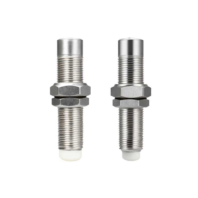
Proximity switches, or proximity sensors, are non-contact devices that detect the presence or absence of an object within their sensing range. They are ubiquitous in industrial automation, found in applications from conveyor belt control to robotic assembly lines. Before any on-site measurement, it is crucial to understand the type of sensor you are dealing with. The primary categories are inductive (for detecting metallic objects), capacitive (for detecting both metallic and non-metallic objects), and ultrasonic. Each type operates on a different physical principle, which directly influences the measurement methodology. Knowing the sensor's specifications—such as its nominal sensing distance (Sn), operating voltage, output type (PNP/NPN, NO/NC), and housing style—is the mandatory first step. Always refer to the manufacturer's datasheet for these critical parameters.
Essential Tools and Safety Precautions
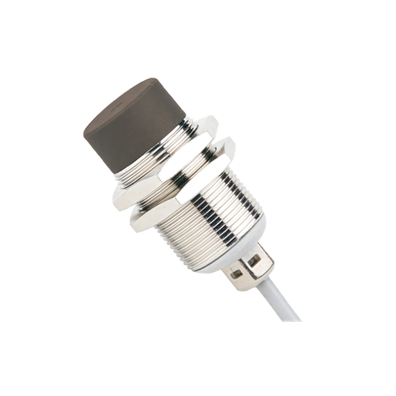
A successful on-site measurement begins with proper preparation. The essential toolkit includes a high-quality digital multimeter (DMM) capable of measuring DC voltage and continuity, an oscilloscope for advanced signal analysis, a reliable distance gauge or set of feeler gauges, and the sensor's technical documentation. Personal Protective Equipment (PPE) is non-negotiable. Ensure the machine or control panel is properly locked out and tagged out (LOTO) before beginning any work. Verify that the power is isolated to the sensor circuit. If testing requires power, exercise extreme caution. Always confirm the voltage levels with your multimeter before making connections to prevent damage to your equipment or the sensor.
Measuring Power Supply and Wiring Integrity
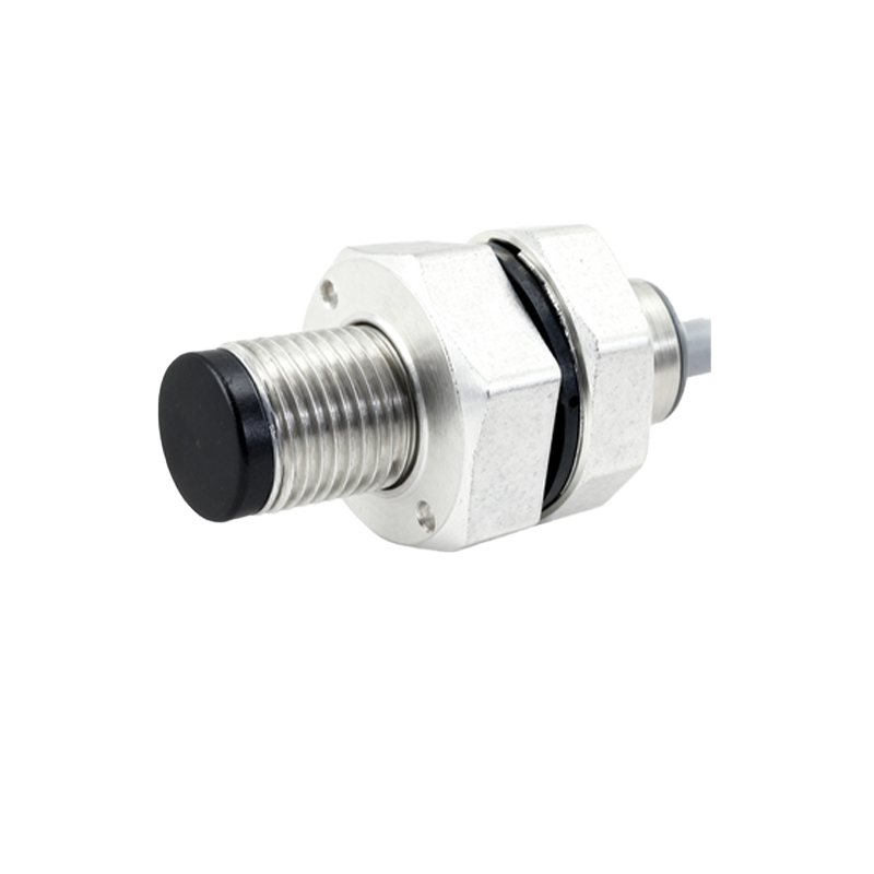
The most common cause of proximity sensor failure is an issue with its power supply or wiring. Start your diagnostics here. With the power safely applied, use your multimeter to measure the voltage between the supply positive (typically brown wire) and supply negative (typically blue wire) at the sensor's connection point. The reading must be within the sensor's specified operating range (e.g., 10-30V DC). A voltage outside this range indicates a problem with the power supply or voltage drop in the wiring. Next, check for wiring integrity. With power off, use the continuity function of your multimeter to check for broken wires, poor connections, or short circuits. Ensure the shield wire, if present, is properly grounded.
Testing Sensor Output and Switching Function
Once power and wiring are confirmed, test the sensor's core function: switching. For a DC 3-wire sensor, identify the output wire (typically black). Connect your multimeter's black probe to the negative (blue) wire and the red probe to the output (black) wire. Set the multimeter to measure DC voltage. Introduce the target object (the correct material and size as specified) into the sensor's sensing field. Observe the voltage change. For a PNP (sourcing) sensor, the voltage should switch from near 0V (object absent) to near the supply voltage (object present). For an NPN (sinking) sensor, the logic is inverted. A failure to switch indicates a faulty sensor. For a 2-wire AC/DC sensor, measure the voltage drop across the sensor under load.
Measuring Actual Sensing Distance and Hysteresis
The rated sensing distance (Sn) is specified for a standard target. In real-world applications, the target material, size, and environmental conditions affect performance. To measure the actual sensing distance, use a precision gauge. Slowly move the standard target toward the sensor's active face. The point at which the output switches state is the "operate point." Record this distance. Then, slowly move the target away. The point where the output reverts is the "release point." The difference between these two points is the hysteresis, a critical parameter that prevents output oscillation. Compare your measured operate point to the datasheet's Sn. A significant reduction may indicate sensor aging, contamination on the face, or misalignment.
Diagnosing Environmental Interference and False Triggers
On-site issues often stem from environmental factors. Electrical noise from nearby motors, VFDs, or welding equipment can cause false triggering. Use an oscilloscope to observe the sensor's output signal line for noise or instability. Capacitive sensors can be falsely triggered by humidity, dust, or chemical deposits on the face. Inductive sensors can be affected by adjacent metal structures (mounting in a metal well) or other sensors in close proximity. Measure the output behavior under the actual operating conditions. Solutions may include installing shielding, using sensors with built-in noise immunity, adjusting sensitivity (if adjustable), or relocating the sensor.