Introduction to Photoelectric Sensors in Elevator Systems
Photoelectric sensors are critical components in modern elevator control and safety systems. These devices utilize light beams to detect the presence or absence of objects, playing a vital role in door operation, car positioning, and passenger safety. An exploded view diagram provides a detailed, disassembled perspective of the sensor, revealing the internal components and their spatial relationships. This guide is designed for maintenance technicians and engineers to understand the construction, function, and assembly sequence of a typical elevator photoelectric sensor through its exploded parts diagram.
Key Components Revealed in the Exploded View
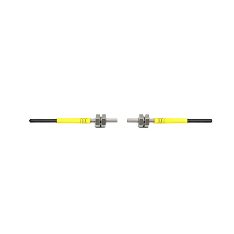
The exploded diagram typically separates the sensor into several core assemblies. The primary housing, often made of durable plastic or metal, protects the internal electronics. Inside, the heart of the device is the printed circuit board (PCB), which hosts the emitter and receiver elements—usually infrared LEDs and phototransistors or photodiodes. The lens assembly, crucial for focusing and directing the light beam, is shown as a separate component. Wiring harnesses and connector terminals are displayed to illustrate electrical connections. Mounting brackets, adjustment screws, and sealing gaskets for environmental protection are also distinctly itemized in the diagram, showing how they interface with the main body.
Function and Interaction of Internal Parts
Understanding how these parts interact is essential for troubleshooting. The emitter LED on the PCB generates a modulated infrared light beam. This beam passes through a precisely molded lens, which collimates it into a narrow, directed path. The receiver lens on the opposite side collects any reflected or transmitted light and focuses it onto the phototransistor. The PCB processes this signal to determine an object's presence. The exploded view clearly shows the alignment between the emitter lens, receiver lens, and their respective electronic components. Any misalignment during reassembly, as indicated by the diagram's positioning, can lead to sensor malfunction.
Step-by-Step Disassembly and Reassembly Guidance
Referencing the exploded view, disassembly begins with removing the external mounting bracket and unplugging the electrical connector. Next, the outer housing's fastening screws or clips, shown in the diagram, are detached to separate the two halves. Care must be taken with the internal PCB, which is often secured by small standoffs or screws. The lens elements can then be gently popped out from their housing slots. The diagram's sequence is reversed for reassembly. It is critical to ensure that all O-rings and gaskets are correctly seated to maintain the sensor's ingress protection (IP) rating, a detail prominently featured in the exploded parts list.
Common Failure Points and Diagnostic Tips
The exploded diagram aids in diagnosing common failures. Accumulated dust or debris on the lens surfaces is a frequent issue, easily identified when the components are separated. Cracked or hazy lenses, visible once disassembled, will scatter the light beam. Failed emitter or receiver components on the PCB require board-level replacement or a full unit swap. Loose wiring at the terminal blocks, clearly shown in the diagram's connection points, can cause intermittent faults. Corrosion on contacts or damaged sealing gaskets, highlighted in the parts view, indicate potential water or moisture ingress problems.
Importance of Correct Alignment and Calibration
After any maintenance involving disassembly, precise realignment is paramount. The exploded diagram provides reference points for the optical axis alignment between the emitter and receiver modules. Many sensors include adjustment screws for fine-tuning the beam's path, and their location and function are specified in the diagram's callouts. Incorrect alignment can lead to false detections or a complete failure to detect objects, compromising door safety. Calibration often involves using a test target and monitoring the sensor's output signal, a process guided by knowing the exact internal component layout.
Safety Precautions and Best Practices
Always disconnect elevator power and follow lockout-tagout procedures before working on sensors. Use the exploded diagram as a reference to avoid forcing components during disassembly. Handle the PCB and optical elements with care to avoid electrostatic discharge (ESD) damage and fingerprints. When reassembling, tighten screws to the manufacturer's specified torque, often noted in the diagram's documentation, to avoid damaging plastic housings. Always perform a full functional test of the elevator door operation and safety circuits after sensor maintenance or replacement.
Conclusion and Reference to Technical Documentation
An exploded view diagram is an indispensable tool for the effective maintenance of elevator photoelectric sensors. It transforms a sealed unit into a comprehensible collection of parts, demystifying its operation and repair. For specific models, always consult the manufacturer's official service manual, which contains the definitive exploded view, part numbers, and detailed specifications. Proper use of this resource ensures repairs are conducted efficiently, safely, and in a manner that restores the sensor to its original operational integrity, ensuring reliable elevator performance and passenger safety.