Understanding the Basic Function and Types
Proximity sensors are critical components in modern industrial automation, detecting the presence or absence of an object without physical contact. Common types include inductive sensors for metallic targets, capacitive sensors for both metallic and non-metallic materials, and photoelectric sensors using light beams. Before testing, it is essential to know the sensor's type, specifications (such as sensing distance, output type - PNP or NPN, NO or NC), and its intended application. A mismatch between the sensor's capabilities and the application can lead to perceived failure. Always refer to the manufacturer's datasheet for the correct operating parameters, including supply voltage range, output current, and environmental ratings like IP class for ingress protection.
Initial Visual and Physical Inspection
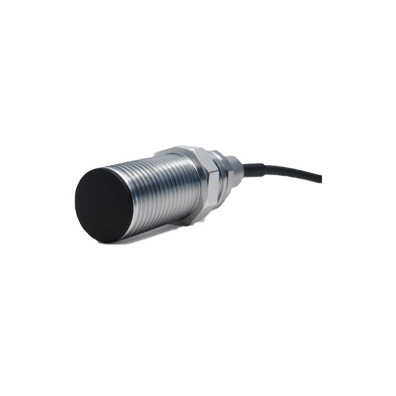
The first and simplest step is a thorough visual and physical examination. Look for obvious signs of damage such as cracks in the housing, bent or broken sensing faces, or corrosion on the electrical connections. Check the cable for cuts, abrasions, or pinch points, especially near the entry point into the sensor body or the connector. Ensure the sensor is mounted securely and correctly; loose mounting can alter the sensing distance and cause intermittent operation. For cylindrical sensors, verify that the locking nut is tight. Also, inspect the target object itself. A change in the target's material, size, or surface finish can affect performance, particularly for inductive and capacitive sensors.
Verifying Power Supply and Wiring
A significant percentage of sensor "failures" are due to incorrect power or wiring. Using a digital multimeter, verify that the correct voltage (e.g., 10-30 VDC for most DC sensors) is present at the sensor's power terminals with stable levels and minimal ripple. Ensure proper grounding. Next, check the wiring against the datasheet diagram. Confusing PNP (sourcing) and NNP (sinking) wiring is a common error. For a 3-wire sensor, typically, brown is positive (+V), blue is negative (0V/common), and black is the output signal wire. For 4-wire sensors, which often have two outputs, confirm the wiring for each. Also, ensure the load (e.g., PLC input, relay coil) is connected correctly and its impedance is within the sensor's specified switching capacity.
Testing Sensor Output Response
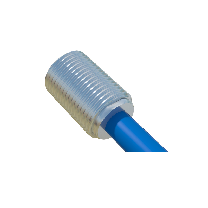
With power correctly applied, test the sensor's switching behavior. Monitor the output signal voltage using a multimeter or an oscilloscope for a more dynamic view. For a normally open (NO) sensor, the output voltage should be low (near 0V for PNP, near supply voltage for NPN) when no target is present. When a valid target is brought within the specified sensing range, the output should switch state. Use the actual target material and move it steadily into the sensing field. Observe if the sensor activates at the correct distance (check repeatability, not just the maximum range) and if the output is clean and stable without chatter. For analog output sensors, measure if the output current (e.g., 4-20mA) or voltage changes smoothly and linearly with distance.
Assessing Environmental and Interference Factors
Environmental conditions can severely impact sensor performance. Inductive sensors can be affected by nearby metal objects, other sensors, or strong electromagnetic fields, causing false triggering. Capacitive sensors are sensitive to changes in humidity, temperature, or the presence of dust, chips, or conductive fluids on the sensing face. Photoelectric sensors can be blinded by ambient light, dirt on the lens, or fog. Test the sensor in its actual operating environment. Temporarily shield the sensor from potential interference sources to see if performance improves. Ensure the sensor's temperature rating is not exceeded. For harsh environments, the buildup of contaminants on the sensing face is a frequent cause of failure.
Using Diagnostic Tools and Advanced Techniques
Beyond a multimeter, several tools aid in diagnosis. An LED indicator is built into most sensors; its behavior (steady on, blinking, off) often provides a diagnostic code—consult the manual for its meaning. A sensor tester or simulator can independently power the sensor and simulate a load, isolating it from the machine's control system. For network-connected IO-Link sensors, use configuration software to read detailed diagnostic data, parameters, and real-time process values, which can pinpoint issues like under-voltage, overload, short circuits, or temperature warnings. Signal analysis with an oscilloscope can reveal noise, slow switching times, or unstable outputs invisible to a multimeter.
Bench Testing and Final Verification
If the sensor fails tests in the application, perform a controlled bench test. Disconnect it from the machine