Understanding Proximity Sensor Fundamentals
Proximity sensors are non-contact devices designed to detect the presence or absence of an object within a specified sensing range. They are ubiquitous in industrial automation, serving critical roles in positioning, counting, and safety applications. Common types include inductive sensors for metallic objects, capacitive sensors for both metallic and non-metallic materials, and photoelectric sensors using light beams. Their operation hinges on generating an electromagnetic field or light beam and detecting changes caused by a target object's intrusion. A failure in these sensors can lead to unplanned downtime, production defects, or even safety hazards. Therefore, a systematic understanding of potential failure modes and their underlying causes is paramount for maintenance personnel and system designers.
Common Symptoms of Proximity Sensor Malfunction
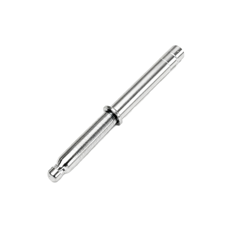
Recognizing the signs of a failing sensor is the first step in troubleshooting. The most frequent symptom is intermittent operation, where the sensor output flickers or becomes unreliable when a target is present. This often manifests as missed counts or erratic machine behavior. Another clear indicator is a complete lack of response; the sensor fails to detect any object, regardless of distance or material. Conversely, a sensor may exhibit constant activation, providing a continuous output signal even when no target is within its sensing field. Inconsistent sensing range is also a telltale sign; the sensor may only detect objects at a fraction of its specified nominal range or may become overly sensitive, triggering from objects far outside its intended zone. Output signal drift, where the switching point becomes unstable over time, further points to an impending failure.
Primary Causes of Inductive Sensor Failures
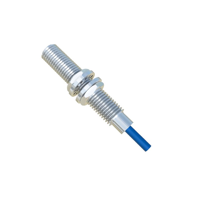
Inductive proximity sensors, used for detecting metals, are susceptible to several specific failure mechanisms. Electrical overload is a leading cause, often resulting from incorrect wiring, short circuits, or voltage spikes on the supply lines, which can permanently damage the sensor's internal oscillator and output circuitry. Physical damage to the sensing face is another common issue. Accumulation of metallic swarf, chips, or conductive dust can create a false "target," causing constant activation or reduced sensing distance. Harsh mechanical impacts can crack the ferrite core or coil assembly, degrading performance. Environmental factors play a significant role; excessive ambient temperature beyond the sensor's specification can cause component degradation, while strong external magnetic fields from nearby motors or transformers can interfere with the sensor's own electromagnetic field, leading to erratic behavior. Finally, using a sensor with an incorrect sensing range for the application, or attempting to detect non-ferrous metals with a standard ferrous-target sensor, will result in perceived failure.
Root Causes for Capacitive and Photoelectric Sensor Issues
Capacitive sensors, which detect changes in capacitance, often fail due to environmental interference. Fluctuations in humidity or the presence of condensation on the sensor face can drastically alter the dielectric constant, causing false triggers or loss of sensitivity. Contaminants like oil, grease, or dust building up on the active surface act as a permanent dielectric, skewing the baseline capacitance. For photoelectric sensors, lens contamination is the primary adversary. Dirt, oil, or debris on the transmitter or receiver lens attenuates the light beam, reducing the effective sensing range or causing complete failure. Misalignment in through-beam or retro-reflective setups is a frequent installation error leading to malfunction. Ambient light interference, particularly from high-intensity sources like sunlight or welding arcs, can swamp the sensor's receiver. Additionally, the sensing object itself may be problematic—if it is highly reflective, transparent, or absorbs the specific wavelength of light used, the sensor may not detect it reliably.
Wiring, Power, and Installation-Related Faults
A substantial percentage of sensor "failures" are not due to the sensor itself but to ancillary factors. Incorrect wiring, such as reversing polarity for DC sensors or connecting to an incompatible voltage (e.g., applying 24V to a 10-30V sensor), can cause immediate damage. Loose connections, corroded terminals, or broken cables create intermittent faults that mimic sensor failure. Electrical noise from Variable Frequency Drives (VFDs), solenoids, or communication cables can induce false signals in the sensor's output circuit. Inadequate power supply, with voltage drops or excessive ripple, prevents the sensor from operating within its designed parameters. Mechanical installation errors are equally critical. Mounting the sensor too close to a metal background (for inductive types) can cause shielding effects. Excessive vibration can loosen mounting hardware or internally damage components. Failure to observe the specified mounting distances and sensing ranges for the specific target material is a common design oversight.
Preventive Maintenance and Troubleshooting Strategies
Proactive maintenance is key to maximizing sensor lifespan and reliability. Establish a regular cleaning schedule using