Understanding Series Connection Fundamentals
Connecting photoelectric sensors in series is a common practice in industrial control circuits, particularly when a specific logical condition must be met. In a series configuration, the output signals of two or more sensors are connected in a chain, forming an AND logic function. This means that for the final output circuit to be activated or closed, all sensors in the series string must simultaneously detect their target or be in their "on" state. This setup is fundamentally different from a parallel connection, which creates an OR logic condition. The series method is essential for applications requiring multi-point verification, such as ensuring a robotic cell is clear before initiating a cycle or confirming that multiple parts are correctly positioned on an assembly line. The electrical principle relies on the daisy-chaining of the sensors' switching outputs, typically using the Normally Open (NO) or Normally Closed (NC) contacts, depending on the safety and logic requirements of the system.
Wiring Diagrams and Electrical Considerations
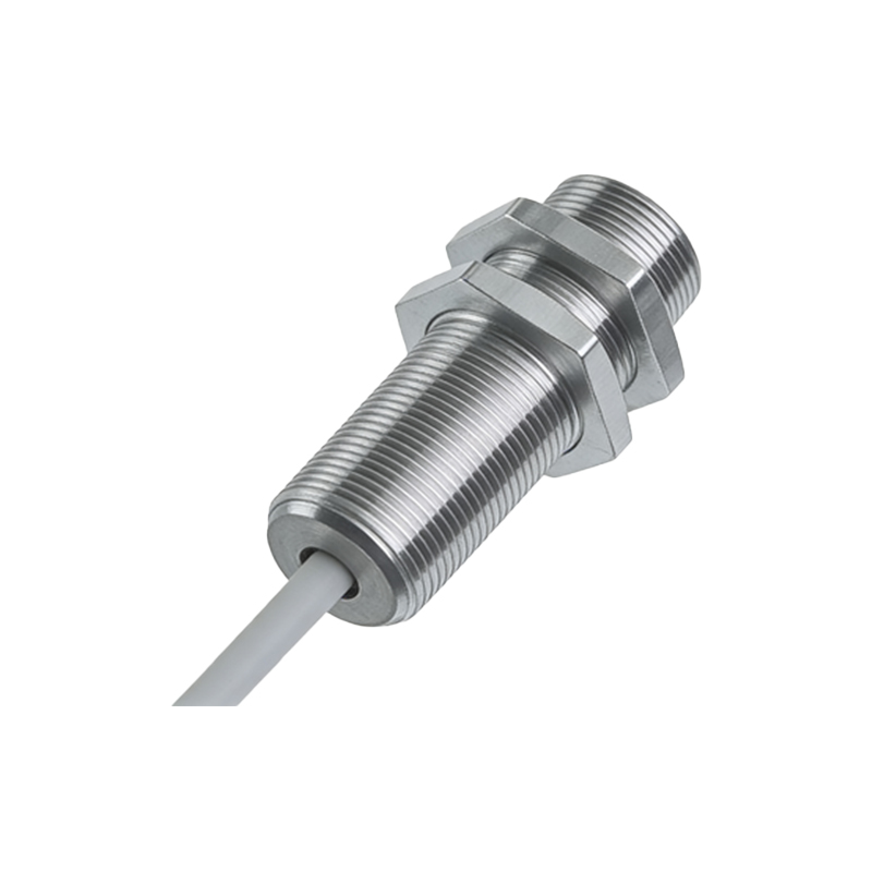
The physical wiring for a series connection is straightforward but requires attention to detail. For DC 3-wire sensors (PNP or NPN), the series connection is made between the output wires. For instance, with two PNP sensors, the switched positive output (often the brown wire for +V, blue for 0V, and black for output) of the first sensor is connected to the positive supply terminal of the second sensor. The final output is then taken from the second sensor's output wire. It is critical to ensure all sensors share a common ground (0V) reference. For AC 2-wire sensors, the series connection is simpler, as the sensors act like switches in the hot line. One side of the first sensor connects to the AC source, the other side connects to one side of the second sensor, and the final load is connected from the second sensor's remaining terminal back to the AC neutral. Engineers must verify the total voltage drop across the series string does not fall below the minimum operating voltage for the load (e.g., a PLC input or relay coil), especially when using many sensors or long wire runs.
Selecting the Right Sensor Type and Output
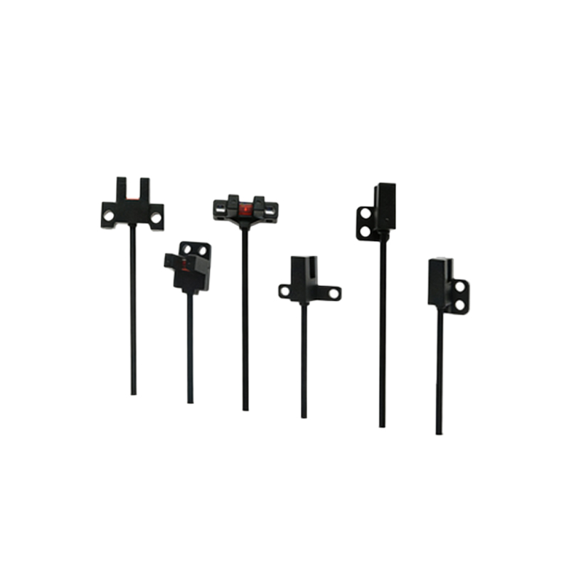
Not all photoelectric sensors are equally suited for series wiring. The choice between relay output, transistor output (NPN/PNP), and solid-state AC output is paramount. Transistor outputs, particularly PNP sourcing types, are very common for DC series circuits in programmable logic controller (PLC) systems. However, one must check the sensor's datasheet for specifications like residual voltage (leakage current) when in the "off" state. In a series chain, even a small leakage current from multiple sensors can accumulate, potentially causing a false "on" signal at the PLC input. For high-reliability or safety-critical applications, sensors with dedicated "series-ready" outputs or those featuring very low leakage current are recommended. Furthermore, the load current rating of each sensor must not be exceeded by the current draw of the subsequent sensors and the final load in the chain.
Practical Applications and System Logic
Series connections are deployed in scenarios demanding guaranteed sequential or simultaneous conditions. A classic example is a light curtain or multiple safety interlock sensors on a machine guard door. All sensors must indicate the guard is fully closed (safe) before the machine's high-power circuits can be energized. Another application is in complex material handling, where a series of through-beam sensors confirms a package's complete traversal through a tunnel, ensuring it has cleared before a diverter gate activates. The logic inherently adds a layer of safety and process integrity. It is also used in energy-saving circuits, where occupancy sensors in different zones of a room are wired in series to control lighting—only when all sensors detect no motion are the lights commanded to turn off.
Troubleshooting Common Series Circuit Issues
Diagnosing faults in a series-connected sensor network can be more challenging than with a single sensor. A single failed sensor or a wiring fault in the chain will break the circuit, causing the entire string to appear "off" or inactive. A systematic approach is required. Begin by measuring voltage at key points in the chain using a multimeter. Check for supply voltage at the first sensor. Then, verify if the output of the first sensor is switching correctly when its sensing condition is met. Proceed down the chain sensor by sensor. Modern sensors with built-in diagnostic LED indicators are invaluable for this process, as they can visually confirm power status and output state. Another common issue is induced electrical noise, especially in long series runs, which can cause erratic behavior. Proper shielding, grounding, and the use of twisted-pair cables are essential mitigation strategies. Always consult the manufacturer's guidelines for maximum allowable cable lengths and noise immunity specifications.
Advantages and Limitations of the Series Method
The primary advantage of connecting photoelectric sensors in series is the enforced logical AND condition, which enhances system safety and process control precision. It simplifies control logic within the PLC, as multiple physical conditions are resolved into a single input signal, potentially saving valuable I/O points. The wiring can also be more efficient in terms of cable routing compared to bringing every sensor's output back to a central panel. However, significant limitations exist. As noted, troubleshooting is more complex. The system's reliability becomes dependent on every single sensor in the chain; the failure of one causes failure of the entire function. There are also electrical limitations regarding cumulative voltage drop and leakage current. For these reasons, critical safety systems often use redundant, independently wired sensors monitored by a specialized safety PLC, rather than a simple hardwired series connection, to achieve higher Safety Integrity Levels (SIL or PL).