Understanding Photoelectric Sensors and GPIO Fundamentals
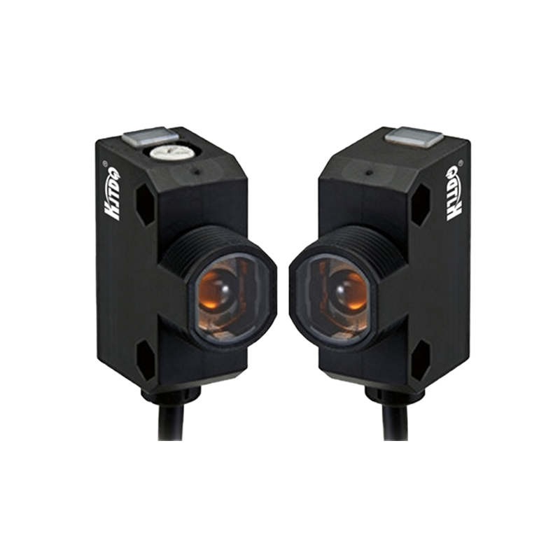
A photoelectric sensor is a device that uses a light transmitter and receiver to detect the presence, absence, or distance of an object. Common types include through-beam, retro-reflective, and diffuse reflective sensors. The output is typically a digital signal indicating a detection event. General-Purpose Input/Output (GPIO) pins are the fundamental interface on microcontrollers and single-board computers like Raspberry Pi, Arduino, or industrial PLC modules. These pins can be configured programmatically as either an input to read a voltage state (high/low) or an output to set a voltage state. For sensor interfacing, a GPIO pin is usually set as an input to read the sensor's digital output signal. Understanding the voltage levels (e.g., 3.3V vs. 5V logic) and the current-sourcing/sinking capabilities of your GPIO is crucial before connecting any external device to prevent hardware damage.
Sensor Selection and Electrical Interface Considerations
Choosing the correct photoelectric sensor is the first step. Key specifications include sensing type, sensing range, output type, supply voltage, and output configuration. For GPIO control, a sensor with a digital output (NPN open-collector or PNP) is required. You must match the sensor's output circuit with your microcontroller's input requirements. A common challenge is interfacing an NPN sensor (sinking output) with a 3.3V microcontroller. The NPN output pulls the signal line to ground (0V) when active, which is readable. However, when inactive, the line is "floating," which can cause erratic readings. A pull-up resistor (e.g., 10kΩ) to the microcontroller's logic voltage (3.3V or 5V) is essential to provide a defined high state. Always consult the sensor's datasheet for its output characteristics and the microcontroller's datasheet for its GPIO input voltage thresholds and maximum ratings.
Circuit Design and Safe Connection Practices
A basic connection diagram involves three main parts: power, sensor, and microcontroller. First, provide a stable DC power supply to the sensor as per its voltage rating (commonly 12-24V DC). The sensor's ground must be connected to the power supply ground and the microcontroller's ground, establishing a common reference. Connect the sensor's digital output wire to your chosen GPIO pin. If using an NPN sensor, connect a pull-up resistor between this GPIO pin and the microcontroller's positive logic supply (3.3V). For added protection, especially in electrically noisy industrial environments, consider using an optocoupler isolator. This device separates the sensor's higher voltage circuit from the delicate microcontroller, transmitting the signal via light, thereby preventing ground loops and voltage spikes from damaging the GPIO. Always double-check connections before powering on.
GPIO Configuration and Software Implementation
Once the hardware is correctly wired, the next step is software configuration. Using a platform like Raspberry Pi (with Python) or Arduino (C++), you must initialize the GPIO pin as an input. In Python using the RPi.GPIO library, you would callGPIO.setup(pin_number, GPIO.IN, pull_up_down=GPIO.PUD_UP). ThePUD_UP parameter internally enables the pull-up resistor if your physical circuit doesn't have one. For Arduino, usepinMode(pin_number, INPUT_PULLUP). The logic level read by the code will depend on the sensor and circuit. Typically, an NPN sensor with a pull-up resistor will present a HIGH (or 1) voltage when no object is detected and a LOW (or 0) voltage when an object is detected. Your main program loop should continuously read the pin state usingGPIO.input() ordigitalRead() and trigger appropriate actions, such as incrementing a counter, activating an actuator, or sending a network alert.
Noise Immunity, Debouncing, and Advanced Techniques
In real-world applications, electrical noise can cause false triggers. Software debouncing is a critical technique to ensure reliability. Instead of reacting to a single state change, your code should confirm the state remains stable for a short period (e.g., 10-50 milliseconds). This filters out transient noise spikes. Implementing a simple debounce function involves recording a timestamp on the first detection and verifying the state is still the same after the debounce delay. For high-speed counting applications, consider using hardware interrupts. Instead of polling the GPIO pin in a loop, you can configure the microcontroller to execute a specific interrupt service routine (ISR) immediately when the pin state changes. This provides a much faster and more efficient response. However, keep ISR code extremely short to avoid system performance issues. For complex systems, integrating the sensor data into a SCADA or IoT platform via communication protocols like MQTT can be the next step.
Troubleshooting Common Issues and Best Practices
If the sensor is not working as expected, follow a systematic approach. First, verify power and ground connections with a multimeter. Check if the sensor's indicator LED (if present) activates upon detection, confirming basic sensor operation. Next, probe the sensor's output wire relative to ground to see if the voltage toggles correctly. If the voltage changes but the microcontroller doesn't register it, verify the GPIO pin configuration and logic level compatibility. Ensure the pull-up resistor is correctly installed if needed. Environmental factors like ambient light (for optical sensors), dust, or vibration can also affect performance. Shield the sensor from stray light and keep the lens clean. As a best practice, always use datasheets, implement proper grounding, include protection circuits, write robust debounced code, and thoroughly test under expected operating conditions before deployment.