Understanding Proximity Sensor Fundamentals
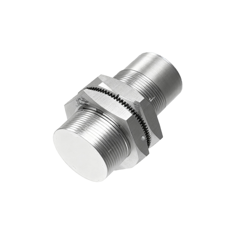
Proximity sensors are critical components in industrial automation, detecting the presence or absence of objects without physical contact. Common types include inductive, capacitive, and photoelectric sensors. Inductive sensors detect metallic objects, capacitive sensors sense both metallic and non-metallic materials, and photoelectric sensors use light beams for detection. Before debugging, it's essential to verify the sensor type, specifications (such as sensing range, output type, and voltage rating), and intended application. Misidentification can lead to incorrect troubleshooting steps. Always refer to the manufacturer's datasheet for technical details.
Pre-Debugging Safety and Preparation
Safety is paramount when working with industrial equipment. Ensure the system is powered down and locked out according to safety protocols before handling sensors. Gather necessary tools, including a multimeter, oscilloscope (for advanced diagnostics), and the sensor's manual. Inspect the sensor and its environment for physical damage, contamination, or obstructions. Check wiring connections for looseness or corrosion. Confirm that the power supply matches the sensor's requirements (e.g., 10-30V DC for many models). Proper preparation minimizes risks and streamlines the debugging process.
Step-by-Step Debugging Procedure
Begin by powering the system and observing the sensor's indicator LED, which typically shows operational status. If the LED doesn't illuminate, check power and ground connections with a multimeter. For sensors with output issues, measure the output signal under different conditions. For example, with a normally open sensor, the output voltage should switch when a target enters the sensing range. If the output is inconsistent, adjust the sensor's sensitivity or distance settings if available. Ensure the target object is within the specified sensing range and moves at an appropriate speed. For photoelectric sensors, clean the lens and verify alignment.
Common Issues and Solutions
Frequent problems include false triggering, no detection, or intermittent operation. False triggering often results from environmental interference, such as electrical noise or nearby metallic objects. Use shielded cables and ensure proper grounding to mitigate noise. For no detection, verify the target material compatibility—inductive sensors won't detect plastics, for instance. Increase sensitivity gradually, but avoid over-sensitivity that causes erratic behavior. Intermittent issues may stem from vibration or temperature fluctuations; secure mounting and selecting sensors with robust environmental ratings can help. Always test with actual operating conditions.
Advanced Diagnostic Techniques
For persistent problems, employ advanced methods. Use an oscilloscope to analyze output waveforms for noise or signal distortion. Monitor current draw to identify internal faults—abnormal current may indicate a failing component. Some programmable sensors offer diagnostic data via software interfaces; utilize these tools for detailed insights. Consider external factors like voltage drops in long cable runs or electromagnetic interference from motors. Document all measurements and changes systematically to track progress and identify patterns. Collaboration with manufacturers' technical support can provide model-specific guidance.
Optimization and Best Practices
After debugging, optimize sensor performance by fine-tuning placement and settings. Ensure the sensor is mounted securely and aligned correctly for consistent detection. Regularly calibrate sensors in high-precision applications. Implement preventive maintenance schedules, including periodic cleaning and inspection. Train personnel on basic troubleshooting to reduce downtime. Keep spare sensors and documentation on hand for quick replacements. By following these practices, you can enhance system reliability and extend sensor lifespan, contributing to efficient industrial operations.