Introduction to Proximity Sensor Functionality
Proximity sensors are indispensable components in modern industrial automation, providing non-contact detection of metallic or non-metallic objects. Their reliability is paramount for ensuring continuous production flow, machine safety, and process accuracy. These sensors operate on various principles, including inductive, capacitive, ultrasonic, and photoelectric technologies. Inductive sensors, for instance, generate an electromagnetic field to detect metallic targets, while capacitive sensors can detect a wider range of materials by sensing changes in capacitance. Despite their robust design for harsh industrial environments, proximity sensors are not immune to failure. Understanding the root causes of these failures is critical for maintenance personnel to implement effective troubleshooting strategies and minimize costly downtime.
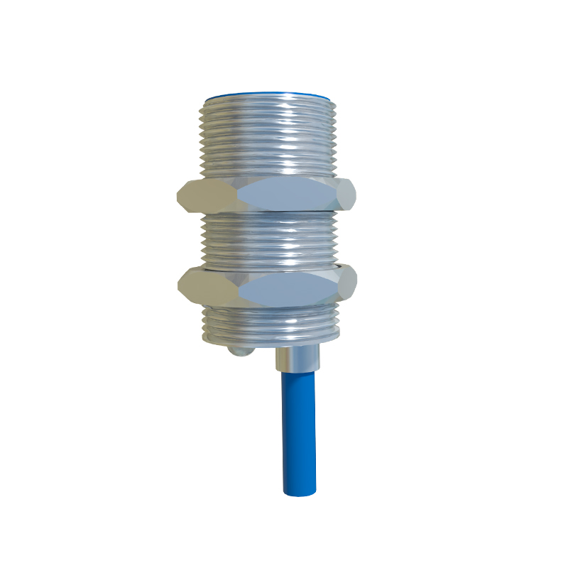
Environmental Contamination and Physical Damage
The operating environment is a primary contributor to proximity sensor malfunctions. Industrial settings often expose sensors to contaminants such as metal chips, dust, oil, coolant, and other conductive or non-conductive debris. For inductive sensors, metallic swarf can adhere to the sensing face, effectively shielding the electromagnetic field and causing the sensor to remain in a falsely activated state or reducing its effective sensing range. Similarly, buildup of grease or other insulating materials on a capacitive sensor's face can impede its ability to detect targets accurately. Beyond contamination, physical damage is a frequent issue. Impacts from machinery, tools, or the targets themselves can crack the sensor housing, damage the sensing face, or misalign internal components. Vibration, if not adequately dampened by proper mounting, can lead to loose connections, internal component fatigue, and eventual failure.
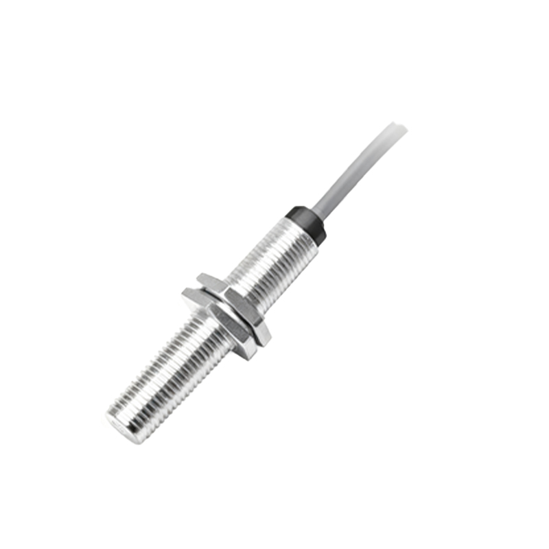
Electrical Overload and Wiring Issues
Electrical problems represent a significant portion of proximity sensor failures. Voltage spikes and transients on the supply lines, often originating from inductive loads like solenoids or motors switching on and off, can overwhelm the sensor's internal circuitry. While many sensors include protective circuits, sustained or extreme surges can cause permanent damage. Incorrect power supply voltage, whether over-voltage or under-voltage, can also lead to erratic behavior or component stress. Wiring faults are equally common. These include short circuits, open circuits, loose terminal connections, and incorrect wiring (e.g., connecting an NPN sensor to a PNP input module, or vice-versa). Poor grounding practices can introduce electrical noise, leading to unreliable switching and false triggering. The integrity of the cable itself is also vital; repeated flexing can break internal conductors, especially at the gland or connection point.
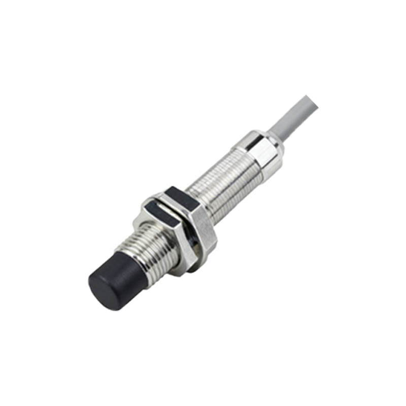
Incorrect Installation and Parameter Settings
Many sensor failures are not due to component defect but to incorrect application and setup. Improper mounting is a typical error. For example, mounting a flush-mountable inductive sensor non-flush in a metal bracket can cause the metal surrounding the sensor to influence its magnetic field, drastically reducing the sensing range or causing permanent activation. Incorrect sensing distance is another factor; operating a sensor too close to its maximum rated distance, especially with small or non-ideal targets, leads to unreliable operation. For adjustable sensors, an improperly set sensitivity or hysteresis level can cause chattering (rapid on/off switching) near the detection threshold. Furthermore, selecting the wrong sensor type for the application—such as using a standard inductive sensor to detect aluminum when a factor-1 version is required—will result in consistent failure to perform as expected.
Internal Component Degradation and Age
Like all electronic devices, proximity sensors have a finite operational lifespan. Internal components, particularly the oscillator circuit in inductive sensors and the output switching transistor, degrade over time. Continuous thermal cycling from power on/off sequences causes expansion and contraction, stressing solder joints and component leads. The output stage, which handles the load current, is susceptible to wear. Frequent switching of high-inrush loads, such as solenoids or contactor coils, can eventually cause the output transistor to fail, typically in a shorted or open state. Environmental factors like extreme temperatures, humidity, and chemical exposure accelerate this aging process. While modern sensors are designed for longevity, eventual failure due to component aging is inevitable and must be planned for within a preventive maintenance schedule.
Troubleshooting Methodology and Preventive Measures
Effective troubleshooting begins with a systematic approach. First, verify the basics: ensure the correct power supply voltage is present at the sensor terminals. Observe the sensor's indicator LED (if equipped) to see if it responds to target presence. Use a multimeter to check the output signal under loaded and unloaded conditions. If the sensor appears dead, inspect for physical damage and contamination. Clean the sensing face thoroughly with appropriate solvents. Check all wiring connections for tightness and corrosion. Review the installation against the datasheet specifications, including mounting, sensing distance, and target material. Implementing preventive measures can drastically reduce failure rates. These include