Proximity sensors are indispensable components in modern industrial automation, offering non-contact detection of metallic and sometimes non-metallic objects. Their reliability hinges not just on selecting the right sensor but, critically, on correct installation. A poorly installed sensor can lead to erratic operation, reduced sensing range, premature failure, and costly downtime. This guide details the essential steps and considerations for installing proximity switches to ensure long-term, trouble-free operation.
1. Pre-Installation Planning and Safety
Before touching any tools, conduct a thorough assessment. First, identify the sensor type: inductive (for metals), capacitive (for metals, liquids, plastics), or ultrasonic. Confirm its specifications—sensing distance, voltage, output type (PNP/NPN, NO/NC)—match your application requirements. Crucially, de-energize the entire circuit. Lock out and tag out (LOTO) the power source to prevent accidental energization during installation. Wear appropriate personal protective equipment (PPE).
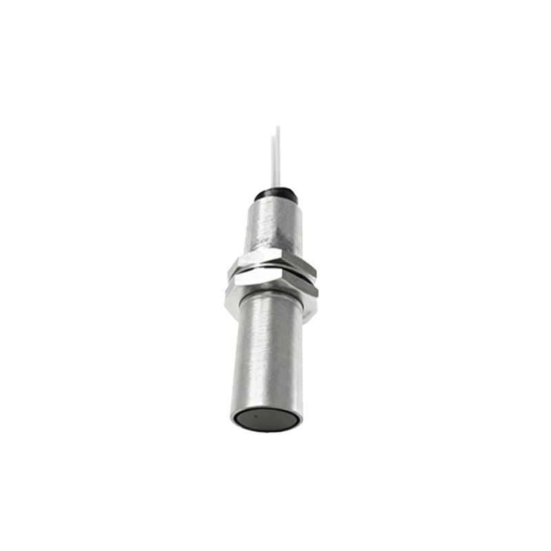
2. Mounting Considerations
Mounting is foundational. For cylindrical sensors, use the correct size bracket or bushing to avoid stressing the housing. Ensure the sensor is securely fastened to prevent vibration-induced loosening or misalignment. The sensing face must be positioned parallel to the target object's approach path. Maintain the specified nominal sensing distance (Sn). A common mistake is installing the sensor too close; always account for operational tolerances, temperature effects, and potential target wear. For flush-mountable sensors, they can be embedded in metal, but non-flush models require a clear lateral clearance zone free of surrounding metal to achieve their rated sensing range.
3. Environmental Protection and Wiring
Environmental factors are a major cause of sensor failure. If the application involves washdowns, coolants, oils, or dust, select a sensor with an appropriate IP (Ingress Protection) or NEMA rating. Even with a high IP rating, avoid directing high-pressure jets directly at the sensor body or cable gland. Proper wiring is non-negotiable. Use shielded cables in electrically noisy environments (e.g., near variable frequency drives, motors, or welding equipment) and ground the shield at the controller end only. Follow the manufacturer's wiring diagram meticulously. Connect the brown wire (typically +V), blue wire (0V/common), and black wire (load/output) correctly. For DC sensors, observe polarity. Keep sensor cables separate from high-voltage power lines to prevent inductive coupling and false triggering.
4. Alignment and Gap Adjustment
Precise alignment is key for consistent detection. The target should approach the sensor's active face squarely. Misalignment can drastically reduce the effective sensing distance. Use a genuine target material of the specified size and shape for final adjustment. After powering up the system, use the target to fine-tune the sensor's position. The optimal installation gap is typically 50-80% of the rated sensing distance to account for mechanical play, thermal expansion, and target variations. Never operate the sensor at its absolute maximum rated distance.
5. Testing and Commissioning
Do not assume correct installation after mounting and wiring. Conduct comprehensive tests. Cycle the target through its normal operational routine at least 10-15 times to verify consistent switching. Check for missed detections or double pulses. Monitor the sensor's output with a multimeter or PLC input indicator to ensure a clean signal. In demanding environments, test under the full range of expected conditions, such as maximum temperature, vibration, or presence of contaminants. Document the installation details, including sensor model, location, and gap setting, for future maintenance.
6. Common Installation Pitfalls to Avoid
Ignoring Temperature Effects: High ambient temperatures can reduce sensing distance and damage the sensor. Ensure adequate ventilation.
Incorrect Target Material/Size: Inductive sensors are calibrated for mild steel. Using stainless steel or aluminum reduces the range. The target must be as large as or larger than the sensor's face.
Multiple Sensor Interference: Mounting two sensors opposite or adjacent to each other can cause mutual interference. Maintain a minimum separation distance (often 2-3 times the sensor diameter) or use sensors with anti-interference technology.
Mechanical Stress: Avoid bending or pulling on the cable. Use strain relief connectors or cable ties to prevent damage to the cable entry point.
Neglecting Regular Maintenance: Periodically inspect sensors for physical damage, buildup of debris on the sensing face, and secure mounting.
By adhering to these systematic installation practices, you maximize the performance, accuracy, and service life of your proximity sensors. A well-installed sensor becomes a reliable and unseen guardian of your automated processes, contributing directly to operational efficiency and productivity.