Introduction to the Downlock Proximity Sensor System
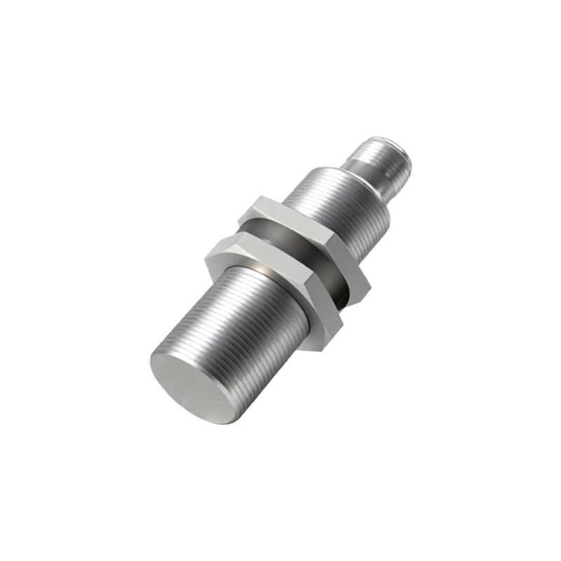
The nose gear downlock proximity sensor is a critical component within the Airbus A320 family's landing gear indication system. Its primary function is to provide a discrete electrical signal to the aircraft's flight deck computers, confirming the physical position of the nose gear downlock mechanism. This confirmation is integral to the safe extension and retraction sequences of the landing gear. The sensor itself is a non-contact, solid-state device, typically of the inductive or Hall-effect type, which detects the presence or absence of the downlock hook's target area. This design eliminates mechanical wear associated with traditional micro-switches, enhancing reliability. The signal generated is fed into the Landing Gear Control and Interface Unit (LGCIU), which processes it alongside data from other gear sensors to illuminate the "three green" lights on the flight deck, providing the pilots with unambiguous confirmation that the nose gear is down and locked.
Technical Principles and Installation
Operating on the principle of electromagnetic induction, the proximity sensor generates an oscillating electromagnetic field. When the metallic target (part of the downlock hook) enters this field, it induces eddy currents within the target, which in turn dampens the sensor's oscillation. This change is detected by the sensor's internal circuitry, causing it to switch its output state. The sensor is precisely mounted on the nose gear shock strut or adjacent structure, aligned with the path of the downlock hook. The alignment gap between the sensor face and the target is a critical installation parameter, specified in the Aircraft Maintenance Manual (AMM). Incorrect gap setting is a common source of erroneous indications. The sensor is connected via a robust, shielded electrical harness to the LGCIU, ensuring signal integrity in the electrically noisy environment of the landing gear bay.
Common Failure Modes and Symptoms
Despite their solid-state design, downlock proximity sensors are susceptible to several failure modes. Environmental contamination is a leading cause; exposure to hydraulic fluid, water, de-icing fluid, and runway debris can degrade sensor performance or cause internal short circuits. Physical damage from foreign object impact or improper handling during maintenance can also occur. Electrically, wiring harness issues such as chafing, broken wires, or corroded connectors often mimic sensor failures. Internally, component aging or manufacturing defects can lead to a "stuck" output signal. The operational symptom is typically an inconsistent or missing "green" light for the nose gear on the flight deck display, often accompanied by ECAM warnings such as "LDG GEAR N NOT LOCKED" or discrepancies between the indication systems of the two independent LGCIUs. Intermittent faults are particularly challenging to diagnose.
Step-by-Step Troubleshooting Methodology
A structured approach is essential for efficient troubleshooting. The process begins with a review of the Aircraft Logbook for any recent related maintenance and a check of the Centralized Fault Display System (CFDS) for current and historic faults related to the LGCIU and landing gear. A physical inspection of the sensor, its mounting, and the associated wiring harness for obvious damage, security, and contamination follows. Using the AMM, technicians then perform specified operational tests, cycling the landing gear (often using the alternate extension system for safety on the ground) while monitoring the sensor's output. This is typically done by measuring resistance or voltage at the sensor connector or at the LGCIU interface using specialized test equipment. A key step is to compare readings with the known-good opposite main gear sensor. BITE (Built-In Test Equipment) functions of the LGCIU can also provide valuable data. The goal is to isolate the fault to the sensor, the wiring, or the computer.
Maintenance, Testing, and Replacement Procedures
Maintenance actions are strictly governed by the AMM. Routine tasks include visual inspections during scheduled checks for security, seal integrity, and cleanliness. Functional testing is performed as part of larger landing gear operational checks. If replacement is required, the procedure mandates electrical power removal from the aircraft, followed by disconnection of the sensor electrical connector. After unbolting the sensor, the critical step is to install the new unit with the correct target gap, using feeler gauges as specified. The gap must be checked and adjusted with the gear in the relevant position (usually down and locked). Post-installation, a full operational test of the landing gear indication system is mandatory. It is crucial to use the correct part number sensor, as different types may have varying electrical characteristics or physical dimensions. All removed components should be tagged and sent for shop repair or scrap as per procedures.
Safety Implications and Best Practices
The integrity of the downlock proximity sensor directly