Introduction to Long-Range Photoelectric Sensor Wiring
Extending the operational reach of photoelectric sensors to distances like 20 meters is a common requirement in large-scale industrial automation, warehouse logistics, and material handling systems. While these sensors are renowned for their non-contact detection capabilities, achieving reliable performance over such lengths necessitates careful attention to the wiring diagram and installation practices. A standard 20-meter cable run introduces significant electrical considerations, primarily voltage drop and increased susceptibility to electrical noise, which can degrade sensor signals and lead to system failures. This guide provides a detailed, professional analysis of the correct wiring methodologies, cable specifications, and circuit configurations essential for maintaining the integrity and reliability of a photoelectric sensor system over a 20-meter distance.
Core Electrical Principles for Extended Distance
The fundamental challenge in long-distance wiring is voltage drop, calculated as V_drop = I * R * L, where I is the current draw, R is the wire resistance per meter, and L is the total cable length (20m). For a typical DC sensor drawing 100mA, using a standard 0.34 mm² (22 AWG) cable with a resistance of approximately 0.054 ohms/meter, the voltage drop over 20 meters would be about 0.108 volts. While this seems minimal, it becomes critical when combined with the inherent resistance of connectors and the minimum operating voltage requirements of the sensor, especially under load variations. Furthermore, the extended cable acts as an antenna, making the system more vulnerable to electromagnetic interference (EMI) from motors, drives, and power lines, which can cause false triggering or signal loss.
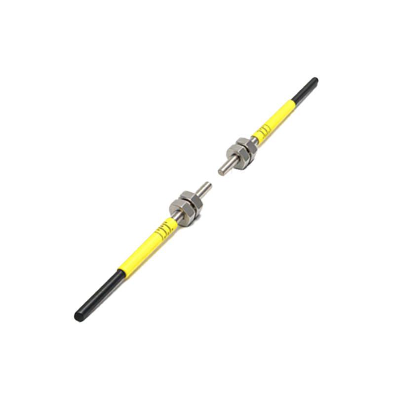
Detailed Wiring Diagram and Configuration
A robust wiring diagram for a 20-meter setup must account for both power supply and signal integrity. For a standard 3-wire DC sensor (Brown: +V, Blue: 0V/Common, Black: Output), the following configuration is recommended. The power supply should be a stable, regulated DC source, sized to deliver the required voltage at the sensor end after accounting for the drop. It is often advisable to use a slightly higher supply voltage (e.g., 26V DC for a 24V DC sensor) or to use a thicker gauge cable. The critical practice is to run the power wires (Brown and Blue) in a twisted pair configuration alongside a dedicated, shielded cable for the output signal (Black). The shield of the cable must be grounded at only one end, typically at the controller or PLC cabinet, to prevent ground loops. All connections must be secure and protected from corrosion.
Cable Specification and Selection Criteria
Selecting the appropriate cable is paramount. For a 20-meter run, it is strongly recommended to use a minimum cable cross-section of 0.5 mm² (20 AWG) for power lines to reduce resistance. Ideally, a multi-conductor, shielded cable designed for industrial sensor applications should be used. This cable typically includes twisted pairs for power and signal within an overall foil or braided shield. The insulation material should be oil-resistant and durable, such as PUR (Polyurethane) or PVC, suitable for the industrial environment. The cable's capacitance per meter is also a factor; lower capacitance helps maintain signal rise/fall times for high-speed switching over long distances.
Power Supply Considerations and Voltage Drop Mitigation
The power supply must be derated for long-distance operation. Calculate the required voltage at the sensor terminals (V_sensor) as: V_sensor = V_supply - (2 * I * R * L). The factor of 2 accounts for both the positive and return paths. For a 24V sensor with a 100mA load, using 0.5 mm² cable (R~0.037 ohms/m), the drop is 2 * 0.1A * 0.037Ω/m * 20m = 0.148V. Therefore, a 24.2V supply at the source would suffice. However, always consult the sensor datasheet for its operational voltage range (e.g., 10-30V DC). Using a local, distributed power supply near the sensor bank or implementing a 24V DC bus with thicker trunk wiring can be more effective solutions for multiple long-range sensors.
Noise Immunity and Signal Integrity Techniques
Ensuring signal integrity over 20 meters requires proactive noise countermeasures. Firstly, always maintain physical separation between sensor cables and high-voltage AC power lines; a minimum distance of 30cm is advised, with crossing at right angles if necessary. Secondly, implement proper grounding: connect the cable shield to the functional earth (FE) terminal in the control panel, ensuring a low-impedance path. For analog output sensors or in extremely noisy environments, using a 4-20mA current loop signal is vastly superior to voltage output, as it is inherently resistant to voltage drop and EMI. For digital sensors, consider using a relay or an opto-isolator module at the controller end to break ground loops and amplify the signal.
Installation, Testing, and Troubleshooting Protocol
During installation, avoid stretching the cable and ensure strain relief is used at both sensor and connector ends. After wiring, perform a comprehensive test. Use a digital multimeter to measure the actual DC voltage at the sensor's terminals under load to confirm it is within specification. Check for continuity and insulation resistance. To troubleshoot instability, temporarily connect the sensor with a short cable to isolate whether the issue is with the sensor or the long wiring. Use an oscilloscope to observe the output signal at the PLC end for noise or attenuation. Common issues include insufficient voltage at the sensor (remedy: increase supply voltage or cable thickness), intermittent signals (remedy: check shield grounding and connections), and false triggers (remedy: increase separation from noise sources, adjust sensor sensitivity).
Conclusion and Best Practices Summary
Successfully implementing a photoelectric sensor with a 20-meter wiring diagram hinges on understanding and mitigating electrical losses and interference. The key takeaways are: utilize a thicker gauge, shielded cable (≥0.5 mm²); calculate and compensate for voltage drop; employ a single-point grounded shield; physically separate signal and power lines; and consider current-output signals for critical applications. By adhering to these industry-standard practices outlined in the wiring diagram, engineers can ensure maximum reliability, longevity, and precision from their long-range photoelectric sensing systems, maintaining optimal performance in demanding automation environments.