Introduction to Current Limiting in Photoelectric Sensors
In traditional photoelectric sensor circuits, a current limiting resistor is a fundamental component. Its primary role is to protect the light-emitting element, typically an LED or laser diode, from excessive current that could lead to premature failure or irreversible damage. The resistor is placed in series with the emitter, and its value is carefully calculated based on the supply voltage and the forward voltage and current specifications of the light source. While effective, this classic approach adds complexity to circuit design, consumes additional board space, and generates extra heat. As sensor technology evolves toward miniaturization and higher integration, the necessity of this discrete component is being re-evaluated. Modern designs are increasingly exploring and implementing architectures that eliminate the need for an external current limiting resistor, paving the way for more compact and efficient solutions.
The Principle of Resistor-Free Photoelectric Sensor Design
The core innovation enabling photoelectric sensors to operate without a traditional series resistor lies in the integration of current regulation directly into the semiconductor device. Instead of relying on a passive resistor to drop voltage, these advanced sensors incorporate an active constant-current driver circuit within the same package as the light-emitting diode. This integrated driver dynamically adjusts its internal impedance to maintain a steady, predefined current flow through the LED, regardless of fluctuations in the supply voltage. This is often achieved through dedicated driver ICs or specially designed ASICs (Application-Specific Integrated Circuits) that are bonded alongside the photonic components. The driver circuit precisely controls the current pulse width and amplitude, ensuring optimal light output for sensing while inherently protecting the diode from overcurrent conditions. This built-in regulation renders the external resistor obsolete.
Key Advantages of Eliminating the Current Limiting Resistor
Removing the external current limiting resistor offers several significant benefits for system design and performance. First, it reduces the component count, which directly lowers the Bill of Materials (BOM) cost and simplifies the PCB layout. This simplification enhances reliability by decreasing the number of potential failure points. Second, it saves valuable space on the circuit board, a critical factor for increasingly miniaturized devices like handheld scanners, wearable tech, and compact industrial sensors. Third, it improves overall power efficiency. A traditional resistor dissipates power as heat (I²R losses), which is wasted energy. An integrated active driver is generally more efficient, minimizing these losses and reducing thermal load on the system. Finally, it can enhance performance consistency. An integrated driver provides more stable and precise current control over temperature and voltage variations compared to a fixed resistor, leading to more consistent light output and improved sensor accuracy and longevity.
Implementation and Circuit Considerations
Implementing a photoelectric sensor without an external resistor requires careful selection of the sensor module itself. Engineers must source sensors that explicitly state they have a built-in constant current driver or are designed for direct connection to a specified voltage rail (e.g., 5V or 12V). The system design focus then shifts to providing a clean, stable power supply with appropriate decoupling capacitors near the sensor module to handle any transient current demands. While the resistor is gone, protection against voltage spikes or reverse polarity might still be necessary, often implemented with a transient voltage suppression (TVS) diode or a series polarity protection diode. Furthermore, for pulsed operation to increase peak light output or reduce average power, the control signal must interface correctly with the sensor's built-in logic, which may include enable pins or modulation inputs. Understanding the datasheet specifications for the forward voltage range and maximum supply voltage of the integrated module is paramount.
Common Applications and Use Cases
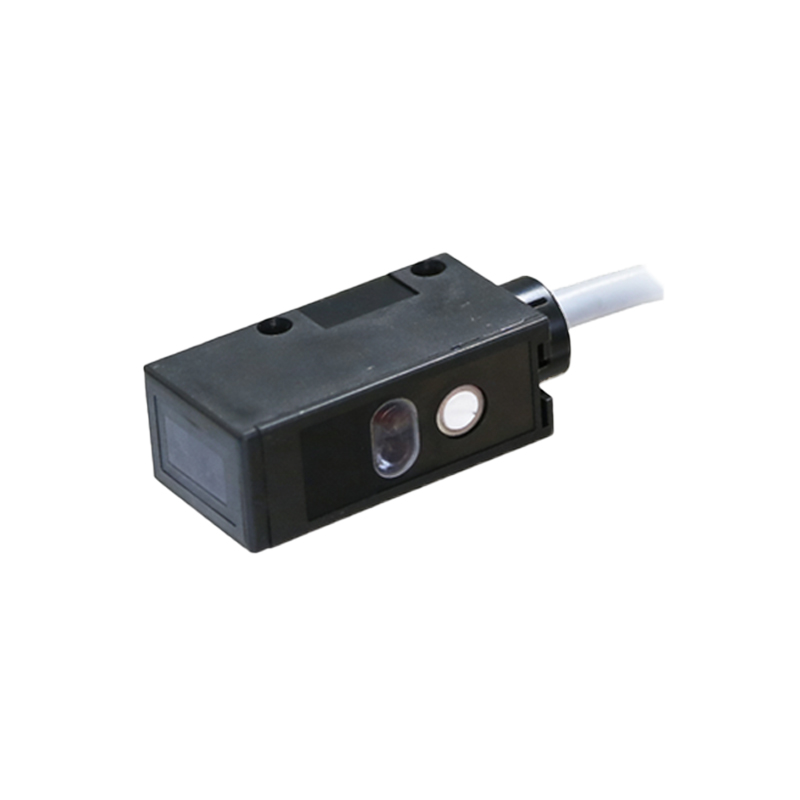
Photoelectric sensors without current limiting resistors are finding widespread adoption across numerous fields. In industrial automation, they are used in compact slot sensors, miniature diffuse sensors, and long-range background suppression sensors for object detection, counting, and positioning on high-speed assembly lines. The consumer electronics industry utilizes them in devices like optical encoders in computer mice, proximity sensors in smartphones, and paper detection sensors in printers. The automotive sector employs them in rain sensors, automatic headlight control, and in-cabin occupancy detection systems, where reliability and space constraints are severe. Additionally, they are ideal for battery-powered Internet of Things (IoT) devices, such as smart meters and environmental monitors, where power efficiency and small form factor are critical for extended operational life.
Potential Challenges and Mitigation Strategies
Despite the advantages, designing with resistor-free photoelectric sensors presents unique challenges. A primary concern is managing heat dissipation. While eliminating resistor heat, the integrated driver and LED still generate heat within a potentially smaller package. Proper thermal management through PCB copper pours or heatsinking may be required for high-current applications. Secondly, these sensors can be more sensitive to electrical noise on the power line due to their active electronics. Enhanced power supply filtering and good EMC (Electromagnetic Compatibility) layout practices are essential. Cost can also be a factor; the integrated sensor module may have a higher unit cost than a simple LED-resistor pair, though this is often offset by the saved assembly and component costs. Finally, designers lose the flexibility of tuning current via resistor value; the operating current is fixed by the internal design, so selecting the right sensor for the required optical output is crucial.
Future Trends in Sensor Integration
The trend toward eliminating discrete passive components like current limiting resistors is part of a broader movement toward higher integration in photoelectric sensing. The future points to "smart sensor" modules that combine the emitter, driver, photodetector, amplifier, and digital signal processor in a single, tiny package. These systems-on-chip (SoCs) will communicate via digital protocols (like I²C or IO-Link), providing not just a switching signal but also diagnostic data such as signal strength, internal temperature, and operating hours. This level of integration will further simplify end-user design, pushing complexity into the integrated module where it can be optimized by the manufacturer. As fabrication technologies advance, we can expect these resistor-free, highly intelligent photoelectric sensors to become the standard, enabling new applications in robotics, augmented reality, and advanced biometric systems where size, power, and intelligence are paramount.