Understanding the Sensor's Working Principle
Before attempting any repair, a thorough understanding of the slot type photoelectric sensor's operation is crucial. These sensors consist of an infrared LED emitter on one side of the slot and a phototransistor or photodiode receiver on the opposite side. The presence of an object within the slot interrupts the light beam, causing a change in the receiver's output state. Common configurations include through-beam and retro-reflective types housed within a single U-shaped body. Familiarity with the specific model's datasheet, including its voltage requirements (typically 5-24V DC), output type (NPN/PNP, NO/NC), and switching characteristics, is the first diagnostic step. Misdiagnosis often stems from incorrect assumptions about the sensor's normal operational parameters.
Initial Inspection and Safety Protocols
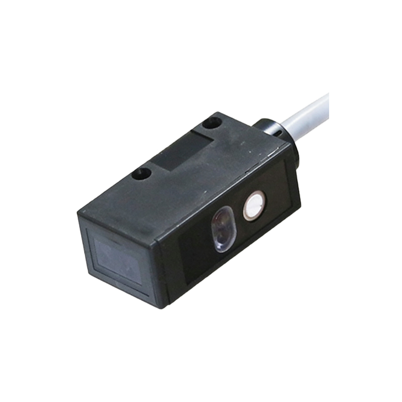
Always begin with a visual and physical inspection. Power down the circuit completely and isolate the sensor. Examine the sensor housing for cracks, discoloration from heat, or signs of physical impact. Check the slot for accumulated dust, oil, or debris that could obstruct the light path. Inspect the wiring leading to the connector for fraying, cuts, or loose terminals. Verify the integrity of the mounting; a misaligned sensor can cause intermittent failures. Safety is paramount: ensure lockout-tagout procedures are followed when working on industrial machinery. Use appropriate personal protective equipment and verify zero energy state before handling connections.
Diagnostic Testing with a Multimeter
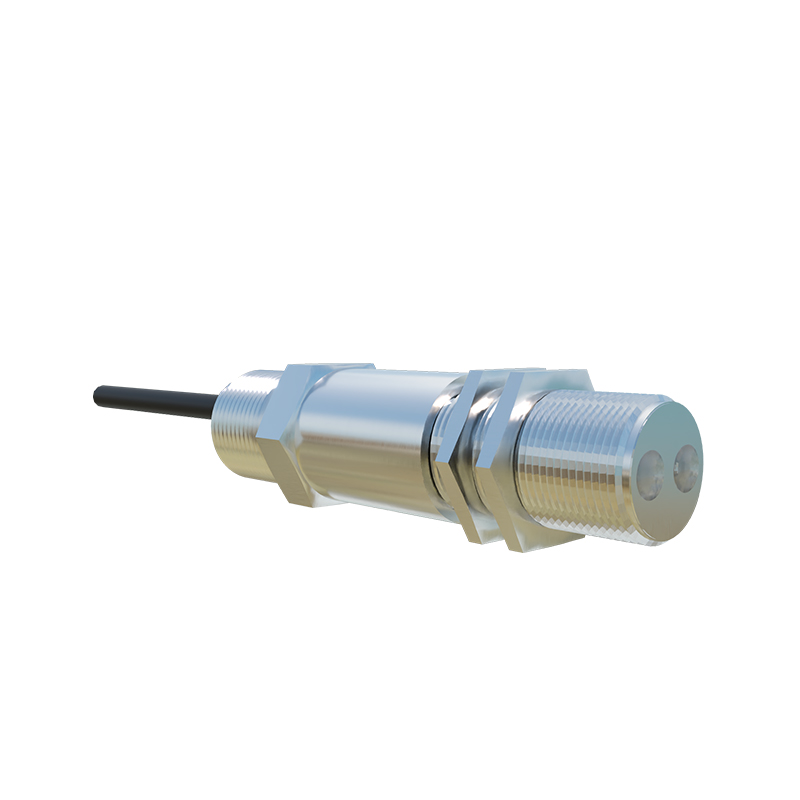
Systematic electrical testing is the core of effective repair. Using a digital multimeter, first check the power supply at the sensor's terminals to confirm it matches the rated voltage. Next, test the output. For a DC sensor, apply power and use the meter in voltage mode. Trigger the sensor by inserting an opaque object into the slot. Observe the output voltage change between the signal wire and common. An NPN sinking output should switch from a high voltage (near supply) to a low voltage (near 0V) when activated. A lack of change indicates a fault. Additionally, test the LED emitter in diode mode; a functional IR LED will show a forward voltage drop typically between 1.1V and 1.6V. A reading of zero or OL suggests a failed emitter.
Cleaning and Optical Path Maintenance
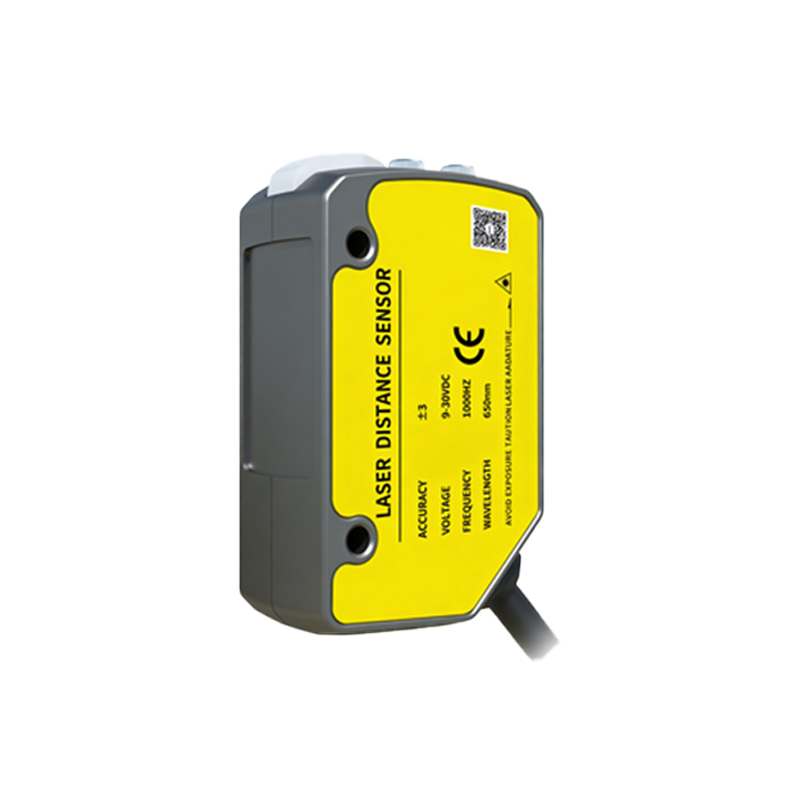
A significant percentage of sensor failures are due to contamination, not electronic failure. Carefully clean the emitter and receiver lenses on both sides of the slot. Use compressed air to blow out loose particles. For stubborn grime, apply a small amount of isopropyl alcohol on a lint-free swab and gently wipe the optical surfaces. Avoid abrasive materials or excessive moisture. Ensure the cleaning agent is completely evaporated before re-energizing. After cleaning, perform a functional test. Also, consider the environment; if contamination is chronic, upgrading to a sensor with a higher IP rating or a built-in air blast feature may be a more sustainable solution than repeated repair.
Component-Level Troubleshooting and Replacement
If power and input signals are correct but the output is faulty, internal component failure is likely. Desolder and remove the sensor from its housing if designed for component access. Common points of failure include the current-limiting resistor for the IR LED, the output transistor (for NPN/PNP types), or voltage regulator ICs. Use the multimeter to test these components in-circuit and out-of-circuit when possible. Replacing a surface-mount resistor or transistor is a standard repair. When replacing the IR LED or phototransistor, pay critical attention to orientation and wavelength matching. Solder with appropriate heat control to avoid damaging the new components or the PCB. Always apply fresh solder and ensure clean, solid joints.
Reassembly, Alignment, and Final Verification
After repair, reassemble the sensor housing carefully, ensuring all seals (like O-rings) are intact and properly seated to maintain the IP rating. Precise realignment is critical for through-beam slot sensors. Use alignment tools or a precise jig to ensure the emitter and receiver faces are perfectly parallel across the slot. Even minor angular misalignment can drastically reduce sensing distance and reliability. Once mounted, perform a full functional verification. Test the sensing repeatability with the target object, check the response time against specifications, and verify the output signal is clean and free of chatter under load. Monitor the sensor's temperature during extended operation to ensure no new faults are present.
Implementing Preventive Maintenance Strategies
Proactive maintenance prevents costly downtime. Establish a regular schedule for inspecting and cleaning sensors in dirty environments. Consider installing protective shrouds or barriers to deflect chips and coolants away from the sensor slot. Use shielded cables and proper grounding in electrically noisy environments to prevent signal interference. Keep a log of sensor failures to identify patterns or problematic locations. For critical applications, maintain a stock of key sensor models for quick replacement, sending the faulty unit for detailed repair offline. Training operational staff to recognize early signs of sensor degradation, such as intermittent operation or decreased sensing range, can facilitate early intervention.